Advanced Sheet Metal Design Using NX Cad Challenge_2_Box Assembly
TITLE:- SHEET METAL BOX ASSEMBLY DESIGN USING SIEMENS-NX.
OBJECTIVE:-
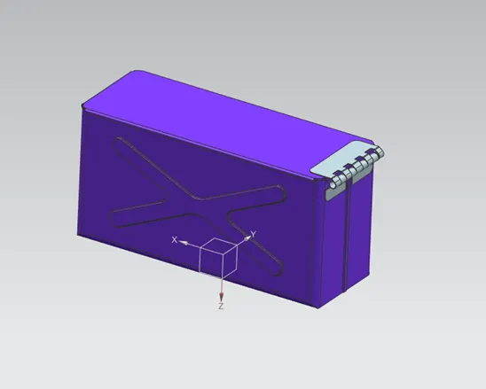
Learn to design a sheet metal Box Assembly by using Siemens NX and write a detailed report on Sheet Metal Component with good explanation on Sheet Metal modelling tools applied throughout the modelling. Also attach the Final model Images (Min. 4 images) of Sheet Metal Box Assembly.
INTRODUCTION:-
Sheet metal parts are widely used in machinery, enclosure, brackets, and automobile due to its various advantages. The parts are normally manufactured with break press. Sheet metal is nothing but the thin sheets made from metal of size ranging from 0.5 to 6mm. In this project I used NX CAD tool for designing the sheet metal bracket. NX CAD is used as design tool in more than 85% of the sheet metal industries.
DESIGN METHODOOLOGY:-
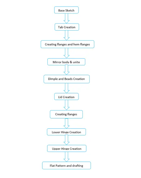
The design methodology used for modeling Box assembly is summarized in below flowchart.
A detailed report on the Design is as follows :-
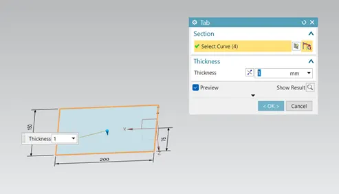
- Tab:-In this box assembly design, lets create the tab by using the sketch on XY plane having dimensions of 150*200 and add tab of given thickness as shown below
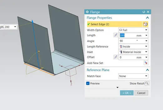
- Flange:-Flange is used to add extra materialto the existing edge at any angle and of any size.let us add four flanges on different edges, firstly creating two flanges with 200 mm length normal to the XY plane and then another two flanges with length of 70 mm are added normal to XZ plane.
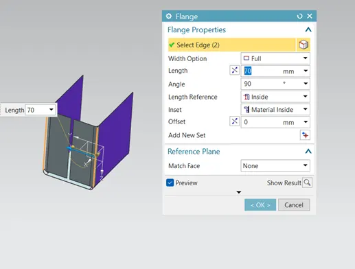
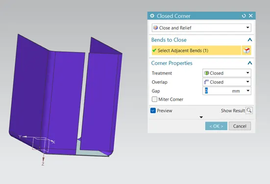
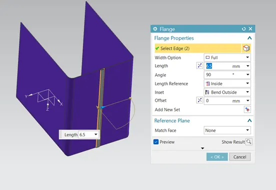
- Closed corner:-Close corner feature is used to close a corner where two adjacent flanges meet by extending the bends and flanges.For fastening or connecting the two flanges on side of box assembly lets model these flanges as shown below
- Hem flange:-Hem flange feature is used to modify the model by folding the edge of a flange. The main purpose of this feature is to increase the stiffness and for safe handling. For this box assembly let us create the hem flanges.
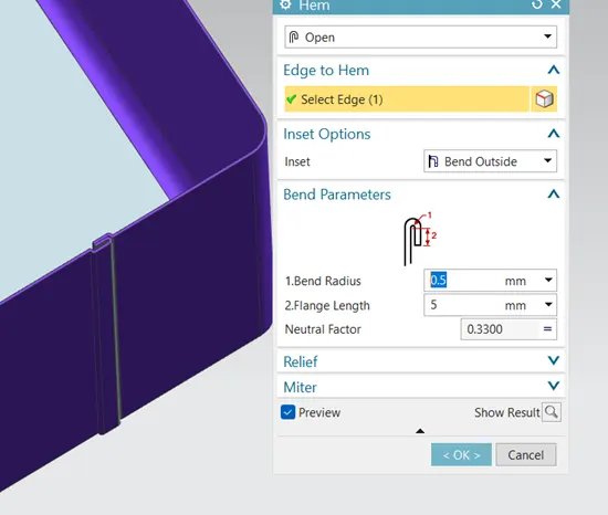
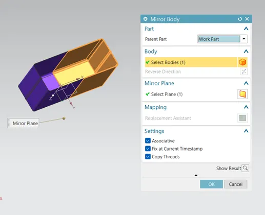
- Mirror body:-Using mirror body feature to mirror the half body about YZ plane.
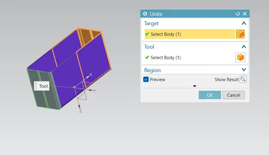
- Unite:-Unite feature is used to combine two different bodies which are in contact. Using unite feature to combine the body before the mirror and after the mirror feature.
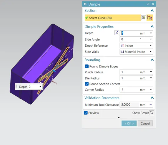
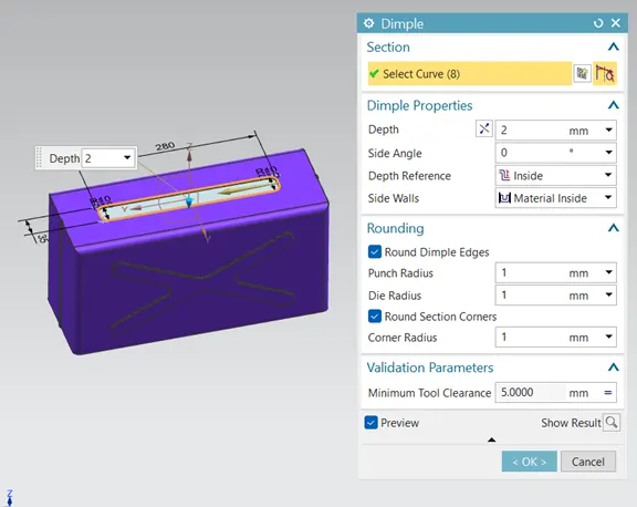
- Dimple:-Add dimple on adjacent sides using given dimensions and use the mirror feature and add another dimple at the bottom side
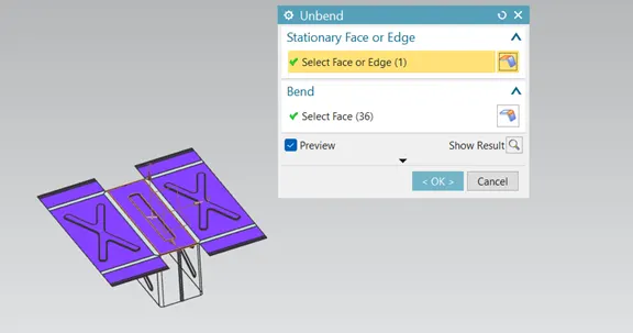
- Unbend and Rebend:-Unbend and rebend the metal sheet.
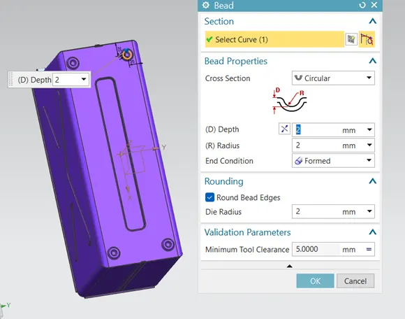
- Beads:-Beads are similar feature like dimple the only difference is that by using dimple we lift an area while in bead we lift the contour of the sketch. It also added to strengthen the component. Adding beads now as shown below.
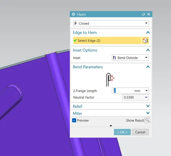
- Add Hem flange:-Add hem along all upper edges of plates using given dimensions.
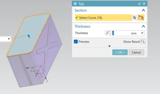
- Lid creation:-For creating the lid for the box, a datum plane was created at a distance of 202 mm from XY plane. The sketch was created by taking the reference of the edges from the top view of the box design. Then the base tab was created with the sketch to create the lid.
- Add flanges:-Add flanges at the top edges of adjacent sides using given dimensions
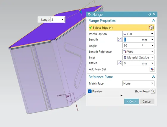
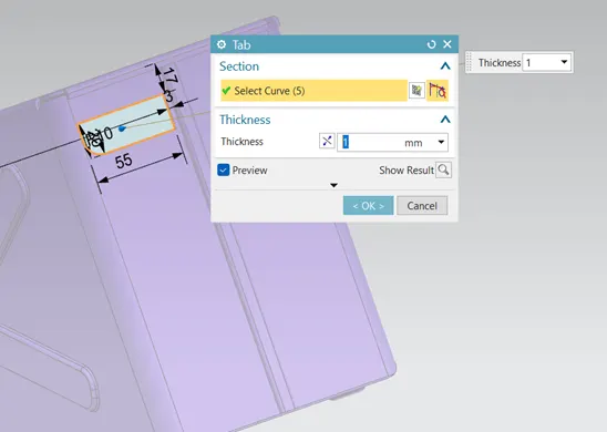
- Hinge: -Let us design the Hinge using followimng steps:
- Tab: -Create new sketch on the back plate and add tab using diven dimensions
- Add flange and hem:- Add flange and hem on the using given dimensions
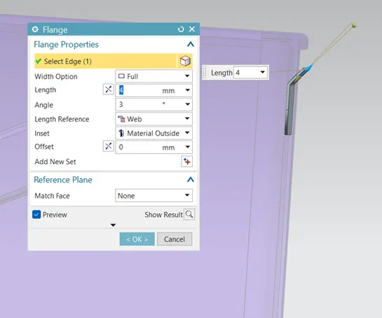
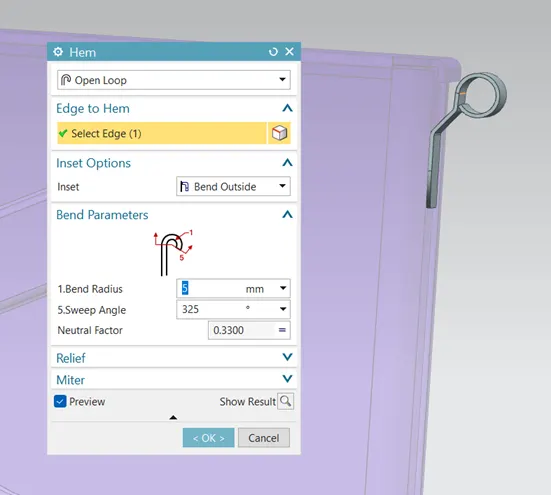
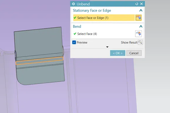
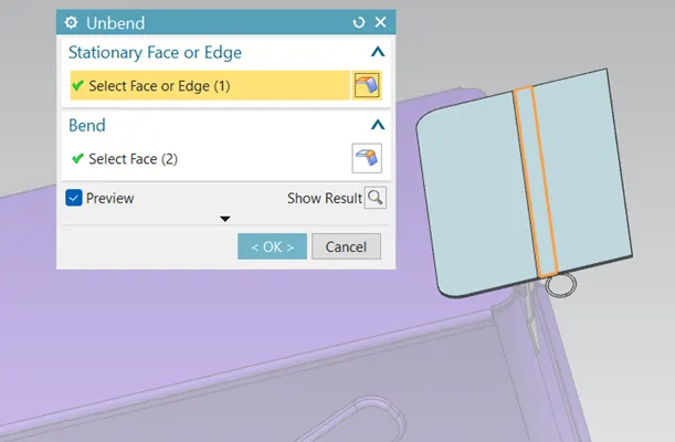
- Unbend :-Unbend the sheet metal to create and cut it out
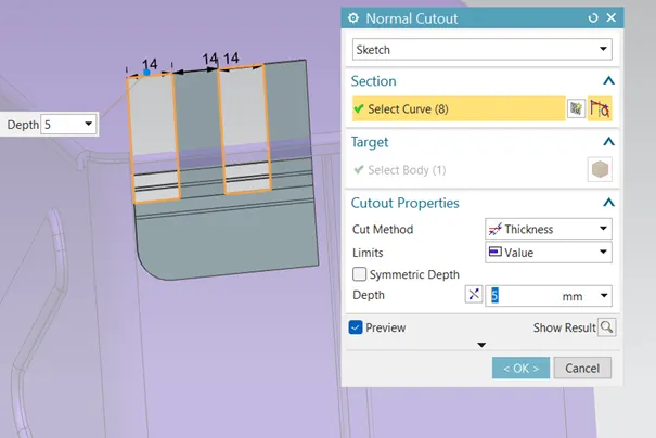
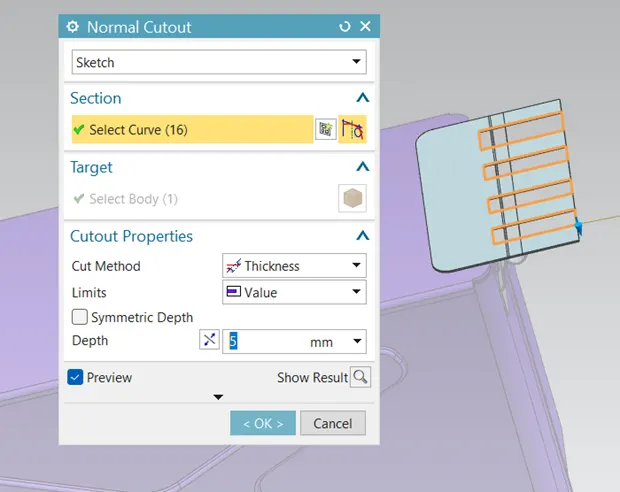
- Make Normal Cutout:-Draw new sketch on the sheet metal surface and use normal cutout feature to create required cutout
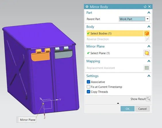
- Rebend & Mirror:-Rebend the metal sheet using rebend command and use mirror body feature to mirror the newly created bodies.
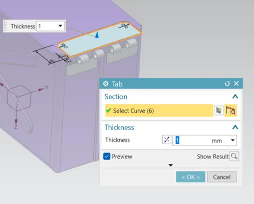
- Tab:- Draw new sketch and create new tab using given dimensions.
- Add flanges and hem:-Add flanges and hem using given dimensions
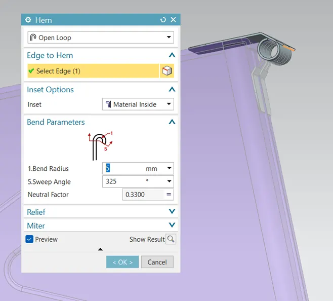
- Unbend and make normal cutout :-Unbend the sheet metal. Draw new sketch and use normal cutout feature to make cut on the sheet metal surface
=Mirror the Normal cutout feature & Rebend the sheet metal to create the hinge.
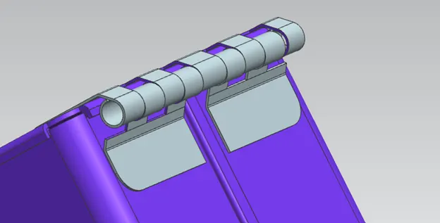
BOX ASSEMBLY IS COMPLETED
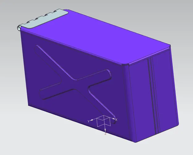
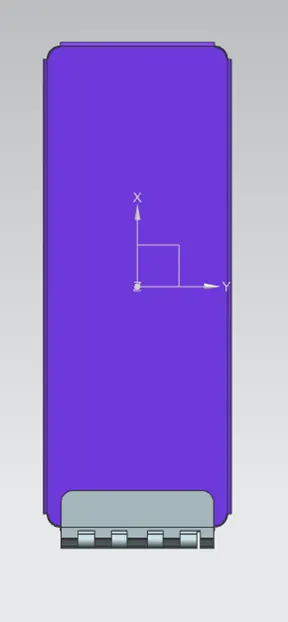
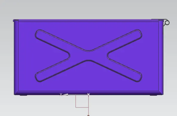
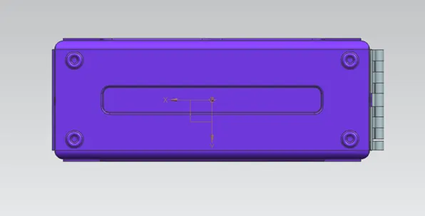
MODEL STANDARD VIEWS
- ISOMETRIC VIEW:-
- TOP VIEW:-
- FRONT VIEW:-
- BOTTOM SIDE VIEW:-
- RIGHT SIDE VIEW:-
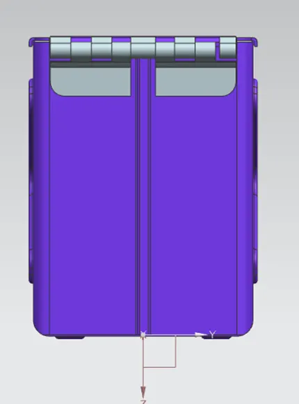
- LEFT SIDE VIEW:-
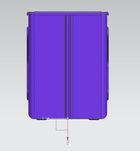
Conclusion:-
Successfully learnt to design a sheet metal Box Assembly in industrial manner by using Siemens NX.