Advanced Sheet Metal Design Using NX Cad Challenge_2_Box Assembly
DESIGN OF A BOX ASSEMBLY USING NX CAD
Objective
The main objective of this project is to design a sheet metal Box assemblyin Siemens NX-cad.
Then Drawing sheet is to be created for the designed sheet metal Box.
INTRODUCTION
- In our box design challenge, we will design a box model by using different tools in NX CAD.
- We will make the drafting of our model.
- The model will consist of a box and a cover with hinges.
Design methodology:
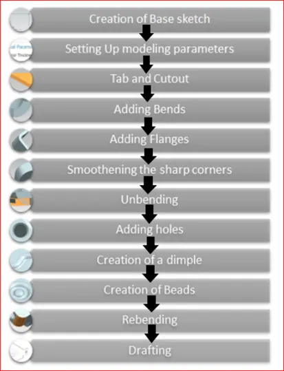
DRAWING THE SKETCH IN SIEMENS NX SHEET METAL:
- After opening Siemens NX 12 – Click on new Button - Select Sheet Metal – In the pop-up window selectSheet Metal– Click ok.
- In the Sheet Metal Window – Click onSketch and select Plane.
- Click on Rectangle Icon located underDirect Sketch Ribbon Bar and draw a rectangle with the center at origin
- Change the design parameters by going to Menu – Preferences – Sheet Metal and then in the Sheet Metal Preferences dialog box set all of the four Global Parameters to 1mm.
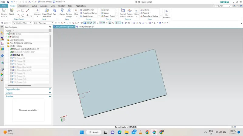
CREATING A TAB:
- Click inTab button to create a rectangular sheet metal of 1mm thickness.
- By default, the section part will be highlighted and hence select the rectangular sketch which is drawn in the previous step – then click ok.
- This will create a Tab of 1mm thickness.
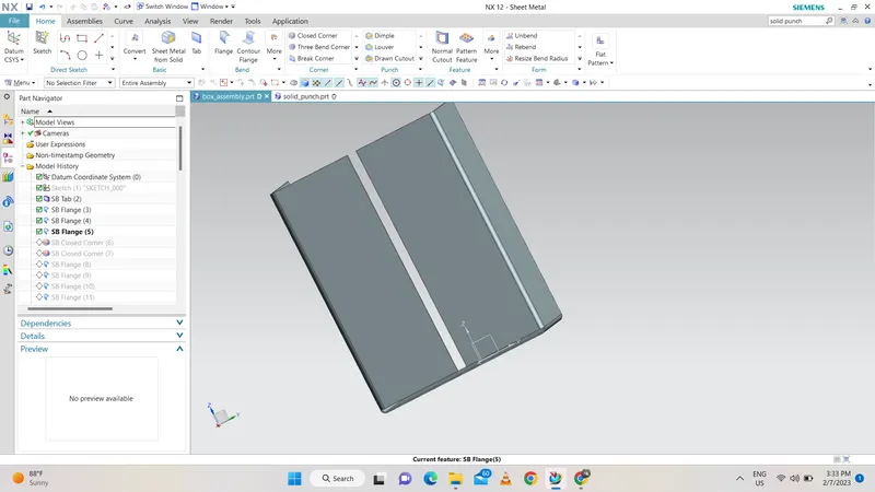
CREATING MULTIPLE FLANGES:
- Click on the Flange button – then select the inner edge of the two longest sides of the rectangle – give the width option as Full – length as 70mm – Angle as 90 degree – Length Reference as Inside – Inset as Material Inside.
- Under the Bend Parameters give the Bend Radius as 10mm and do not change the value of Neutral factor – Give ok or else click on apply and then give cancel.
- Create another two flanges at 90 degrees along the shortest distance of the Tab but should be opposite to each other – give the length as 70mm – length reference as inside – Inset as Material outside – Give the bend radius as 10mm – click ok or else click apply and then click cancel.
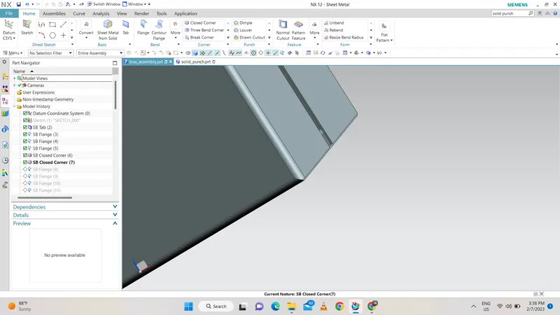
CREATING CLOSED CORNERS:
- Click on the Closed Corner located in the group titled Corner along the Ribbon Bar.
- Select the type as Close and Relief –click zero gap
- Click ok Similarly, do it for the other side also.
CREATING MULTIPLE FLANGES:
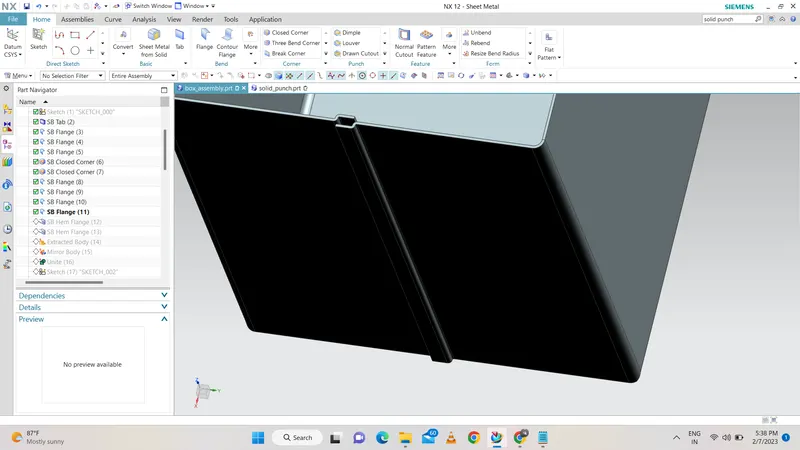
- Click on the flange button then select the vertical inner edge of the flange previously created give the Width option as Full Length as 0.2 Match Face Angle as 90 degree Length Reference as Inside and the Inset Material Inside Bend Radius as and leave the Neutral Factor as it is Click on apply.
- For the second flange select the inner left edge of the newly created flange width option as Full Length as 6.5mm. Match Face Angle as 90 degree. Length Reference as Inside Inset as Bend Outside and Bend Radius as 0.5mm
- For the third flange the outer edge of the opposite flange width option as Full Length as Match Faceangle as 90 degree Length Reference as Web Inset as Material Inside Bend Radius and leave neutral Factor as it is Click on apply
- For the Fourth Flange select the outer edge of the opposite flange width option as Full Length Match Face as None Angle as 90 degree .Length Reference as Web Inset as Bend Outside Bend Radius as 0.5mm and leave neutral Factor
CREATING MULTIPLE HEM FLANGES:
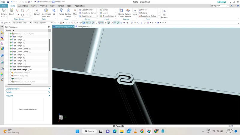
- Create Hem Flanges by clicking on the HEM Flange Icon located under the Group Titled Bend.
- For the first HEM Flange Select Type as open Select the edge of the previously created flange Select Inset as Bend Outside Bend Radius as 0.5 and Flange Length as 5 then Leave the Neutral Factor.
- For Second HEM Flange Select Type as open Select the edge of the outside Flange Select Inset as Bend Outside Bend Radius as 0.5 Flange Length as 5 Leave the Neutral Factor as it is and Click ok or else click on apply and then click on cancel.
- Adjust the Hem flanges so that it meets the requirement.
MIRRORING BODY:
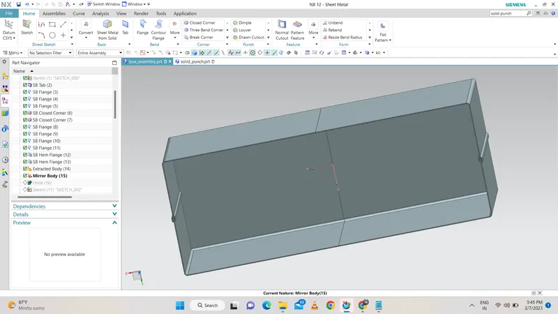
- Click on the Mirror body Button select the entire body of the part Under mirror plane. select the plane Activate all of the three settings available.
UNITING BODY:
- Click on Unite Command available under the Group titled Features Combine.
- Select the entire body part as Target For Tool select the plane Click ok.
ADDING A DIMPLE & MIRRORING IT:
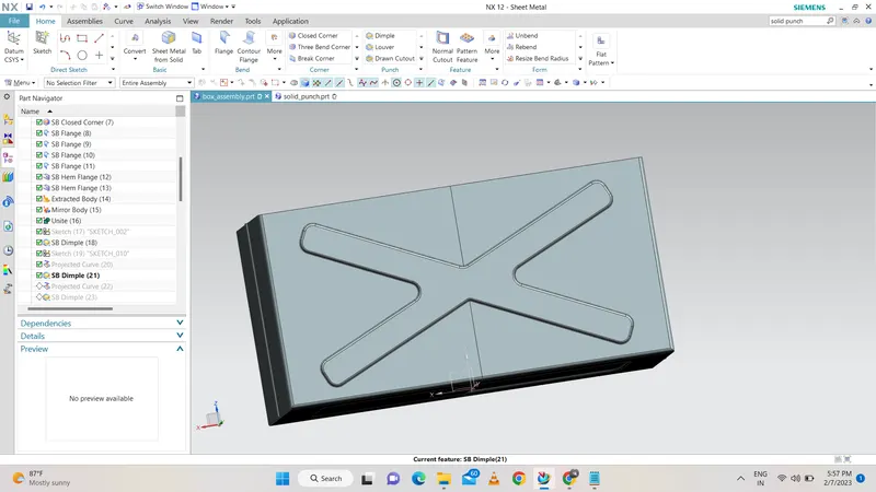
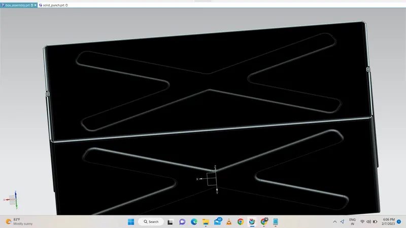
- Click on the Dimple command available under the Group titled Punch click on the sketch button available in the command window.
- sketch the 2D drawing of a cross as per the dimension Mention all the constraints thus required to fully define the sketch Click on Finish in order to finish the sketch.
- Now under the dimple command window give the depth as 2mm Depth Reference as Inside Side Walls as Material Outside and Minimum Clearance as 5mm. The dimple preview should create a dimple towards outer direction if not then click on the button mentioned against Reverse Direction in the Dimple Command Window then click ok.
REBEND:
- Click on the Unbend Button For a stationary Face or Edge Select the bottom rectangular plate of the Assembly box then click, drag and select the entire model thus designed so far This will unbend all the bends thus creating the flat sheet metal with bending lines visible.
- Now click on the Rebend button Click and select the entire box assembly and then click ok.
CREATING A BEAD :
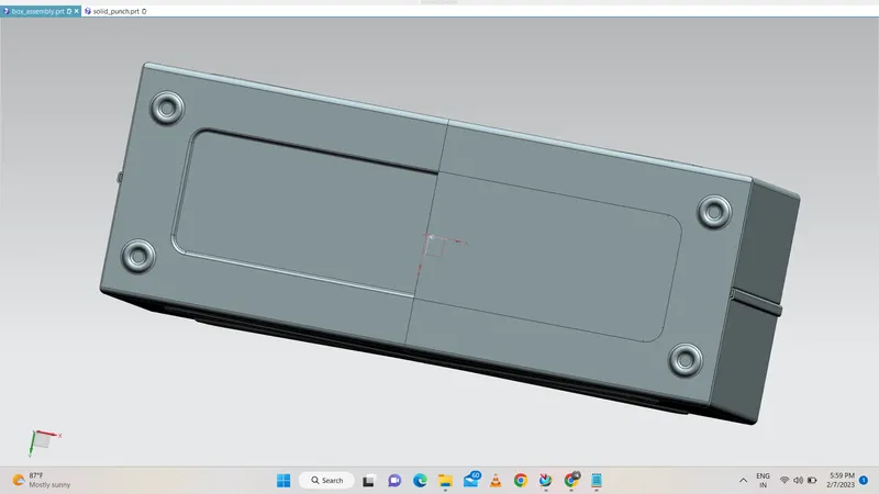
- Now click on the bottom outer plate of the box assembly Click on the Bead button available under the Group Titled Punch which could be seen on the Ribbon Bar.
- Create the required Circular sketch of a given size. select the circular sketch for Stationary Face or Edge. Click on ok
CREATING ANOTHER HEM FLANGES:
- Create another set of HEM Flanges along the outer edges on the top side of the box assembly Select the type as Closed. Select the Inset as Bend Outside.Give the flange length as 2mm.
- Create similar types of HEM Flanges of the same size along all the remaining outer edges.
CREATING A DATUM PLANE:
- Create a Datum plane by clicking on the Datum Plane located in the drop down list box of the Datum Button at the beginning of the Ribbon Bar.
- Select the type as Inferred Select the plane and then give the distance and Click ok.
DESIGNING THE LID:
- Create a new sketch on the newly created plane by clicking on the sketch button and then selecting the new plane thus created.
- Click on the straight-line button available under the group titled Direct Sketch along the Ribbon Bar.
- Draw lines along the border of the flanges thus created so far.
- Create a Tab of thickness 2mm after closing all the gaps in the sketchand click ok.
CREATING MULTIPLE FLANGES FOR THE LID:
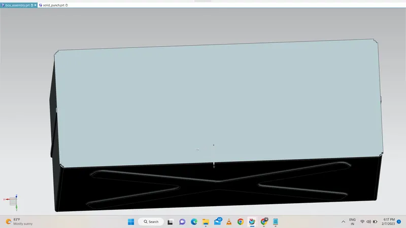
- Create Multiple Flanges at 90 degrees along the outer edges of the lid by clicking on the Flange button located under the group titled Bend.
- For Base Edge Select all the outer bottom edges of the lid Select the width option as Full Length as 3mm. Direction should be downward if not click on Reverse Direction button in the command window Match Face as None Angle as 90 degree Length Reference as Web Inset as Material Outside and Bend radius as 3mm. Leave the default value of Neutral Factor as it is. click ok or else click on apply and then click on cancel.
CREATING HINGES
- Create a sketch on the left side face of the box assembly by clicking on the sketch button and selecting the left side face.
- Draw a Rectangle of approximate size whose right top corner is located at a vertical distance of 17mm from the top surface of the assembly box and having a horizontal distance of 3mm from the right side.
- Create a Tab of thickness 1mm which is projected upward.
- Create a fillet in the part by selecting Break Corners located under the group titled Corners along the Ribbon Bar.
- For Edge to Break Select the top left and right edges of the Tab thus created in previous sessions Select Blend under Method and give the radius as 10mm. click ok or else click on apply and then click on cancel.
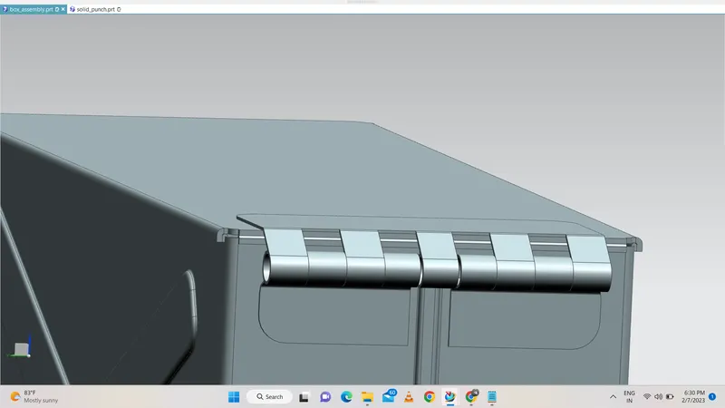
- Create another flange created at the inner edge of the flange thus created Width option Length as 4mm Angle as 40 degree Length reference as Web. Inset as Material outside Bend Radius as 0.5mm and leave the Neutral Factor as it is Click on ok.
- Create a hem flange of type as open type select the outer edge of the flange created in the previous step inset as bend outside bend radius as 5mm. sweep angle as 325degree.
- Unbend the entire flanges and hem flanges thus created so far.
- Create a sketch on the unbend section Draw four Rectangles located at a similar distance from each other Exit the sketch and click on normal cutout. select the type as Sketch Cut method as thickness Limits as value and Depth as 5mm click on ok.
- Rebend again all the flanges and hem flanges.
- Create a mirror body for the part thus created.
- Create a Tab of thickness 1mm on the top of the lid.
- Create break corners on the top two corners of the tab thus created in the previous step.
- Create a flange of length 13mm of bend radius 1mm length reference as Web Inset as material outside Angle as 325 degree. Width option as full click ok.
- Create a hem flange of bend radius 5mm sweep angle 325 degree bend relief as square depth as 3mm width as 3mm inset as bend outside & loop as open-loop.
- Unbend all the flanges and hem flanges thus created.
- Create four rectangles located at equal spaces on this unbend sheet plate.
- Click on normal cut and remove the material inside of these rectangles.
- Rebend again all the flanges and hem flanges.
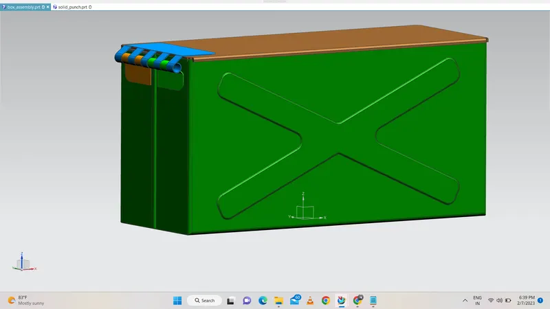
5.17. ADDING COLORS:
- Right-click on each side of the assembly box select Assign Feature Colorand then click on the required color click ok.
- Repeat the same procedure to change the color of the different parts of the box assembly.
5.18. CREATING DRAFT SHEET
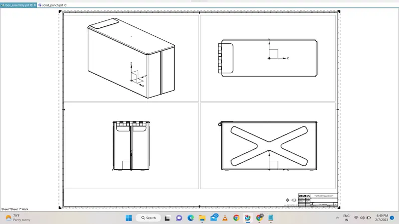
- Click on the Application available on the menu bar select Drafting on the Ribbon bar Click on View Creation Wizard.
- In the View Creation Wizard Dialog box Select the part file.
- Under Option select the scale value as 2:1.
- In the Orientation option select the type of orientation need on the drafting sheet.
- Under Layout option Select the type of layout to be required in the drafting page Click on Finish.
Conclusion
- Here we have drawn our second model Box Assembly by using NX CAD.
- we have created a drafting sheet of the model for future presentation.