Advanced Sheet Metal Design Using NX Cad Challenge_2_Box Assembly
INTRODUCTION
- In our second challenge, we will design a box model by using different tools in NX CAD.
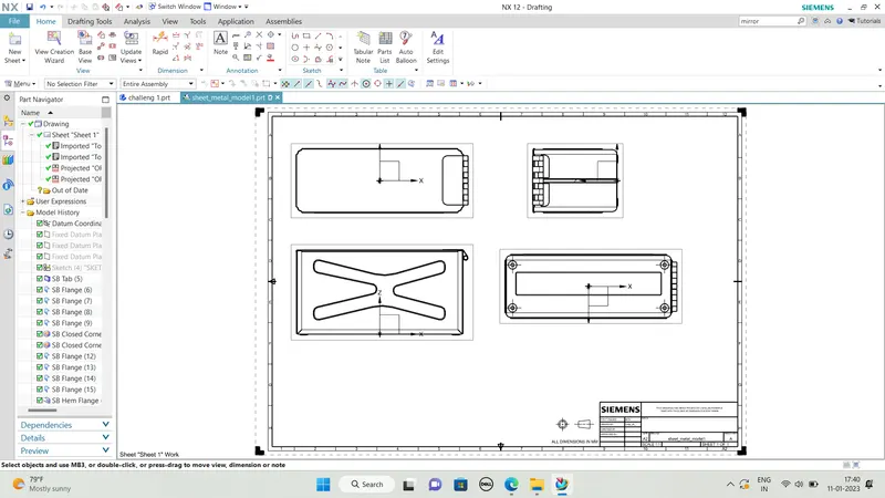
- We will make the drafting of our model.
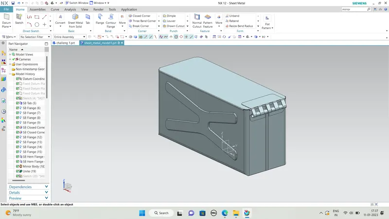
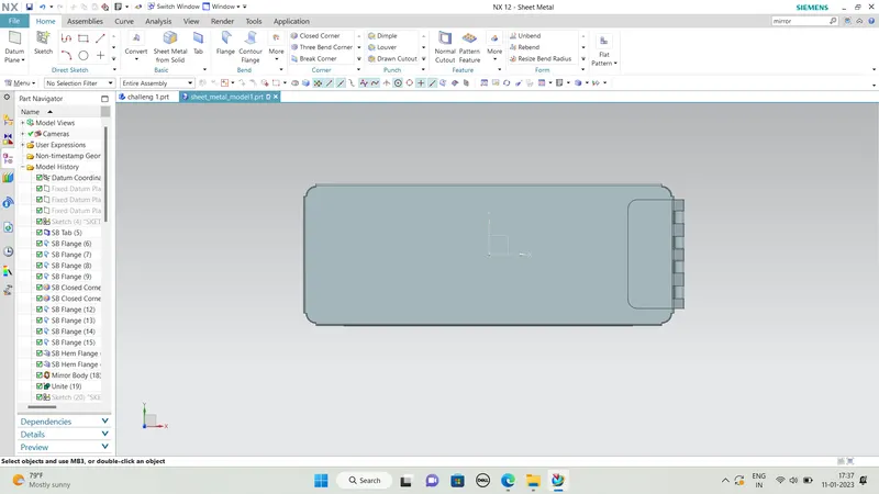
- The model will consist of a box and a cover with hinges.
DESIGN METHODOLOGY / APPROACH
Here we will discuss some of the tools that we are going to be used in the software.
Before proceeding towards the bo design we have to set some parameters for the sheet metal.
First, we will set the Material thickness, bend radius, relief depth, relief width for the model as shown in the image.
Here all the parameters, we will set to 1mm.
COMMANDS USED :
- Tab
- Flange
- Closed Corner
- Break Corner
- Dimple
- Normal Cutout
- Mirror Feature
- Bend
- Unbend
- Rebend
- Hem flange
SHEETMETAL FORMING PROCESS :
-
Sheet metal Bending
-
Sheet metal curling
-
Sheet metal decambering
-
Sheet metal expanding
-
Deep Drawing
-
Hydroforming
-
Incremental Sheet Forming
-
Ironing
-
Laser Cutting
-
Photo chemical Machining
-
Press Brake Forming
-
Punching
-
Rolling
-
Wheeling
DESIGN PROCEDIRE :
Tab
A tab is used to creates a base feature or we can say it add some material on the planer surface as per the sketch.
Here we have drawn a rectangle with some length and width. And after clicking on the tool icon it creates the feature with the given parameters shown in the image.
The length and width of the sketch will be 200mmx150mm.
Flange
Add some flange with the base feature with some width and can create an angle between them.
The length will be 200mm and the bend radius is 10mm.
Closed Corner
It is used to closed the corner of two adjacent flanges.
Here the two corners will be selected.
Dimple
It lifts the area of the model inside the sketch that simulates a stamping tool.
Normal Cutout
It removes material from the model as per the drawn sketch on the surface of the model.
Rebend
It bends the model again as before it had been.
Hem flange
Hem flange is used to bend the model in an open-loop, closed-loop, Sloop, and many more.
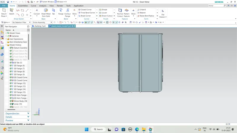
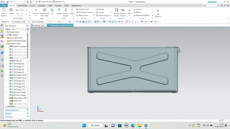
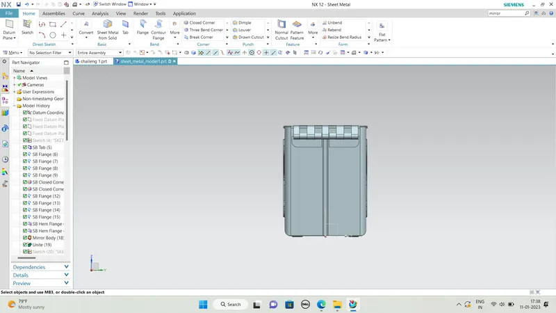
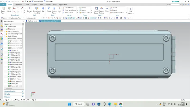
FINAL MODEL OUTPUT :
MODEL DRAFTING :