Advanced Sheet Metal Design Using NX Cad - Box Assembly
DESIGN and MODELLING of SHEETMETAL BOX ASSEMBLY in NX-12
Objective:-
# To design and model the sheet metal Box Assembly in NX-12 by using some basic features and tools.
# To learn to create sketches on defined planes as per requirement.
# To master the user interface and basic features of Sheetmetal application in NX-12 like Tab, Flange, Break corner, Unbend, Rebend, Dimple, Bead, Mirror body, closed corner, and hem.
Introduction:-
Sheet metal Design and Fabrication:-
# Sheet Metal Fabrication is the process of forming parts from a metal sheet by punching, cutting, stamping, and bending.
# 3D CAD files are converted into machine code, which controls a machine to precisely cut and forms the sheets into the final part.
# Sheet metal parts are known for their durability, which makes them great for end-use applications (e.g. chassis). Parts used for low volume prototypes and high volume production runs are most cost-effective due to large initial setup and material costs.
# Because parts are formed from a single sheet of metal, designs must maintain a uniform thickness. Be sure to follow the design requirements and tolerances to ensure parts fall closer to design intent and cutting sheets of metal
Forming Basics:-
1. Bending
Bending is a process whereby a force is applied to sheet metal which causes it to bend at an angle and form the desired shape. Bends can be short or long depending on
what the design requires.
Bending is performed by a press brake machine that can be automatically or manually loaded. Press brakes are available in a variety of different sizes and lengths (20-200 tons) depending on the process requirements.
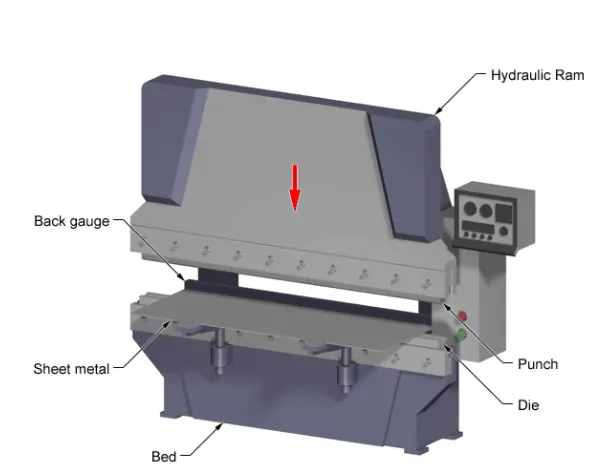
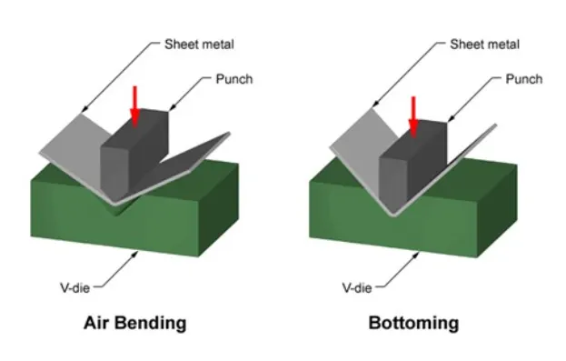
The press brake contains an upper tool called the punch and a lower tool called the die between which the sheet metal is placed. The sheet is placed between the two and held in place by the backstop. The bend angle is determined by the depth that the punch forces the sheet into the die. This depth is precisely controlled to achieve the required bend.
Standard tooling is usually used for the punch and die. Tooling material includes, in order of increasing strength, hardwood, low carbon steel, tool steel, and carbide steel.
Parts to be bent are supplied as flat patterns with bending information. Sometimes bend positions are etched with bend notches, or these notches can be cut out to show the benders where to bend.
Once the laser has cut the flat parts out they can be sent for bending. A press brake forms the flat pattern into a bent part.
2. Critical Dimensions
The following are some terminology that are used in sheet metal. Designers need to adhere to machinery guidelines when designing for bending. Bends can be characterized by these parameters. Some critical dimensions that need to be considered when setting up sheet metal in CAD software are sheet metal thickness, the k-factor, and bend radius. One needs to check that these factors are consistent with the tooling that will be used in manufacturing. This guide gives important guidelines for good design practice.
To prevent parts from fracturing or having distortions, make sure to keep the inside bend radius at least equal to the material thickness
Rule of thumb
It is recommended to use the same radii across all bends, and the flange length must be at least 4 times the material thickness.
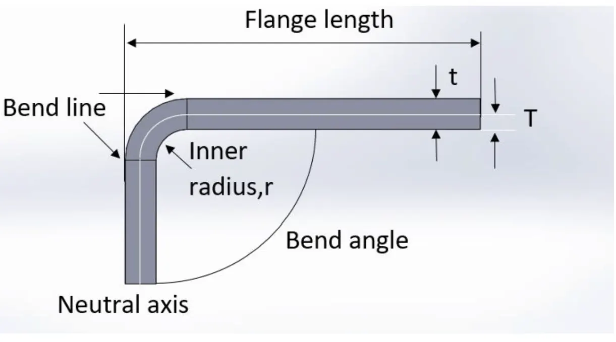
Bend line– The straight line on the surface of the sheet, on either side of the bend, that defines the end of the level flange and the start of the bend.
Bend radius – The distance from the bend axis to the inside surface of the material, between the bend lines.
Sheet metal bend brakes are used to bend the material into the parts desired geometry. Bends that are in the same plane need to be designed in the same direction to avoid part reorientation, to save both money and time. Keeping the bend radius consistent will also make parts more cost-effective. Thick parts tend to become inaccurate so they should be avoided if possible. Small bends to large.
MinimumBend Radius, r – Minimum bend radii requirements can vary depending on applications and material. For aerospace and space applications, the values may be higher. When the radius is less than recommended, this can cause material flow problems in soft material and fracturing in hard material. Localized necking or fracture may also occur in such cases. It is recommended that the minimum inner bend radius should be at least 1 times the material thickness.
MinimumFlange Length, b – This is the minimum length of the bend must be supported all the way until the bend is complete. The flange must be long enough to reach the top of the die after it’s been fully formed. Brake press operators should know the minimum flange lengths for their tooling before attempting bends that may not work and while it is possible to calculate the minimum flange having an Air Bend Force Chart on hand certainly makes it more convenient.
Bend angle – The angle of the bend, measured between the bent flange and its original position, or as the included angle between perpendicular lines drawn from the bend lines. Sometimes specified as the inside bend radius. The outside bend radius is equal to the inside bend radius plus the sheet thickness.
A +/- 1 degree tolerance on all bend angles is generally acceptable in the industry. Flange length must be at least 4 times the material thickness.
Neutral axis – The location in the sheet that is neither stretched nor compressed, and therefore remains at a constant length.
K-factor – The location of the neutral axis in the material, calculated as the ratio of the distance of the neutral axis T, to the material thickness t. The K-factor is dependent upon several factors (material, bending operation, bend angle, etc.) and is greater than 0.25, but cannot exceed 0.50. K factor = T/t
Importance of the K-factor in sheet metal design:-
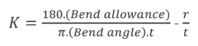
The K-factor is used to calculate flat patterns because it is related to how much material is stretched during bending. Therefore it is important to have the value correct in CAD software. The value of the K-factor should range between 0 – 0,5. To be more exact the K-factor can be calculated taking the average of 3 samples from bent parts and plugging the measurements of bend allowance, bend angle, material thickness, and inner radius into the following formula:
Wall Thickness – Parts need to maintain a uniform wall thickness throughout. Generally, capabilities of 0,9mm – 20mm in thickness are able to be manufactured from a sheet (<3mm) or plate (>3mm) but this tolerance depends mainly on the part.
When considering sheet metal thickness, a single sheet with punches (holes) is a good rule of thumb. Some features such as countersinks are doable but counterbores and other machined features are difficult to produce as they require post-machining.
3. Springback
When bending a piece of sheet metal, the residual stresses in the material will cause the sheet to springback slightly after the bending operation. Due to this elastic recovery, it is necessary to over-bend the sheet a precise amount to achieve the desired bend radius and bend angle. The final bend radius will be greater than initially formed and the final bend angle will be smaller. The ratio of the final bend angle to the initial bend angle is defined as the springback factor, KS. The amount of springback depends upon several factors, including the material, bending operation, and the initial bend angle and bend radius.
4. Bend Relief
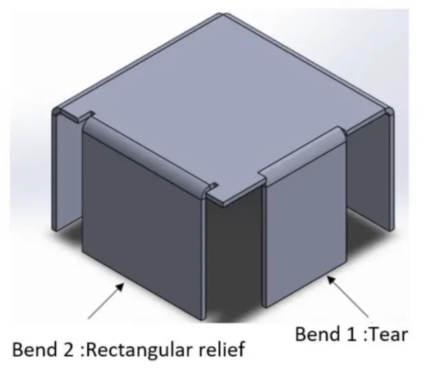
When a bend is made close to an edge the material may tear unless bend relief is given.
Bend 1 shows a tear relief.
Bend 2 shows a rectangular relief cut into the part, the depth of the relief should be greater than the radius of the bend. The width of the relief should be the material thickness or greater.
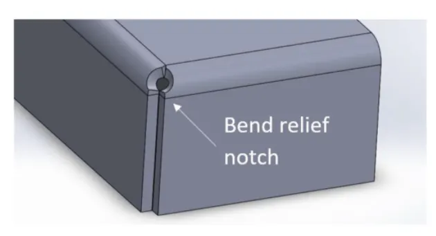
Bend reliefs are utilized where a bend extends on an edge. The relief notch is added to prevent tearing. Bend reliefs will be no deeper than the material thickness plus the bend radius.
5. Bend Height
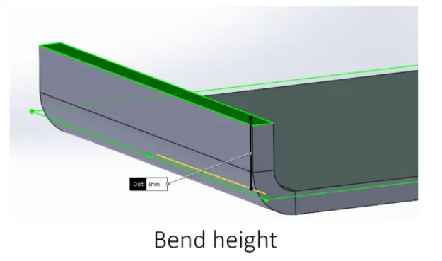
Bend height Sheetmetal bend height should be at least twice the thickness of the sheet metal plus the bend radius. (H=2t + r). If the bending height is too small this will result in deformation and low bending quality.
6. Forming Near Holes
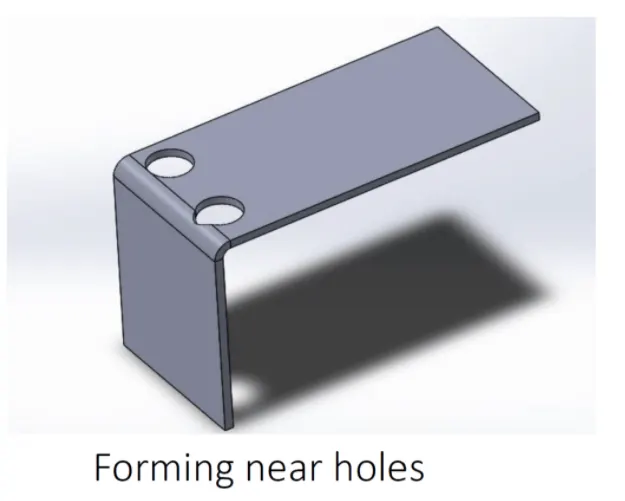
When a bend is made too close to a hole the hole may become deformed. Hole 1 shows a hole that has become teardrop-shaped because of this problem.
To save the cost of punching or drilling in a secondary operation the following formulas can be used to calculate the minimum distance required:
For a slot or hole < 25mm in diameter the minimum distance to Hole 2 center:D = 2t + r
As a rule of thumb, the distance from the outside of the material to the bottom of the cutout should be equal to the minimum flange length as prescribed by the air bend force chart D = 2.5t + r
When using a punch press, or laser cutting, holes should never be less than that of the material thickness
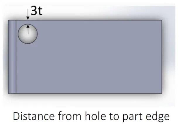
7. Minimum Distance from Extruded Hole to Part Edge
Extruding metal is one of the most extreme pressure applications in press working and generates a lot of friction and heat. If an extruded hole is too close to the part edge, it can lead to deformation or tearing of the metal. It is recommended that the minimum distance between the extruded holes to the part edge should be at least three times the thickness of the sheet.
8. Minimum Distance Between Extruded Holes
Certain distance should be maintained between two extruded holes in sheet metal designs. If extruded holes are too close it can lead to metal deformation. It is recommended that the minimum distance between two extruded holes should be six times the thickness of sheet metal.
9. Minimum Hole Diameter
The diameter of the hole in the sheet metal part should not be very small, small holes are created by the piercing operation and for manufacture small holes, small sizes punches are required. Small hole size in sheet metal requires a smaller size punching tool which may lead to breaking during the operation. It is recommended that the diameter of the hole should be equal or more than the thickness of the sheet metal.
NX delivers a tailored environment for sheet metal design, with onscreen controls and modeling commands for typical features in sheet metal components.
NX Sheet Metal Design includes tools for unfolding bends to create accurate flat patterns for fabrication.
Benefits-
• Intuitive user interface results in the reduced learning curve
• Streamlined workflow requires less time for part design
Features-
• Built-in design intent using a focused sheet metal workflow
• Customer-defined default values
• Intuitive user interface
• Built-in intelligence for ripping and bend relief
Design Methodology / Approach:-
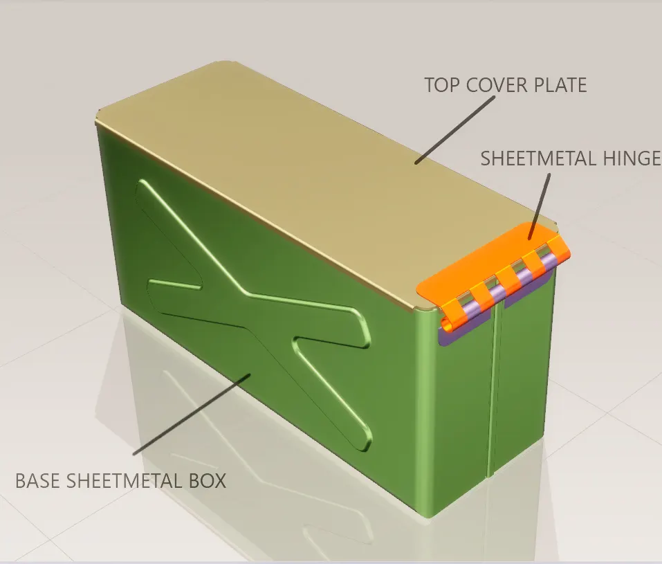
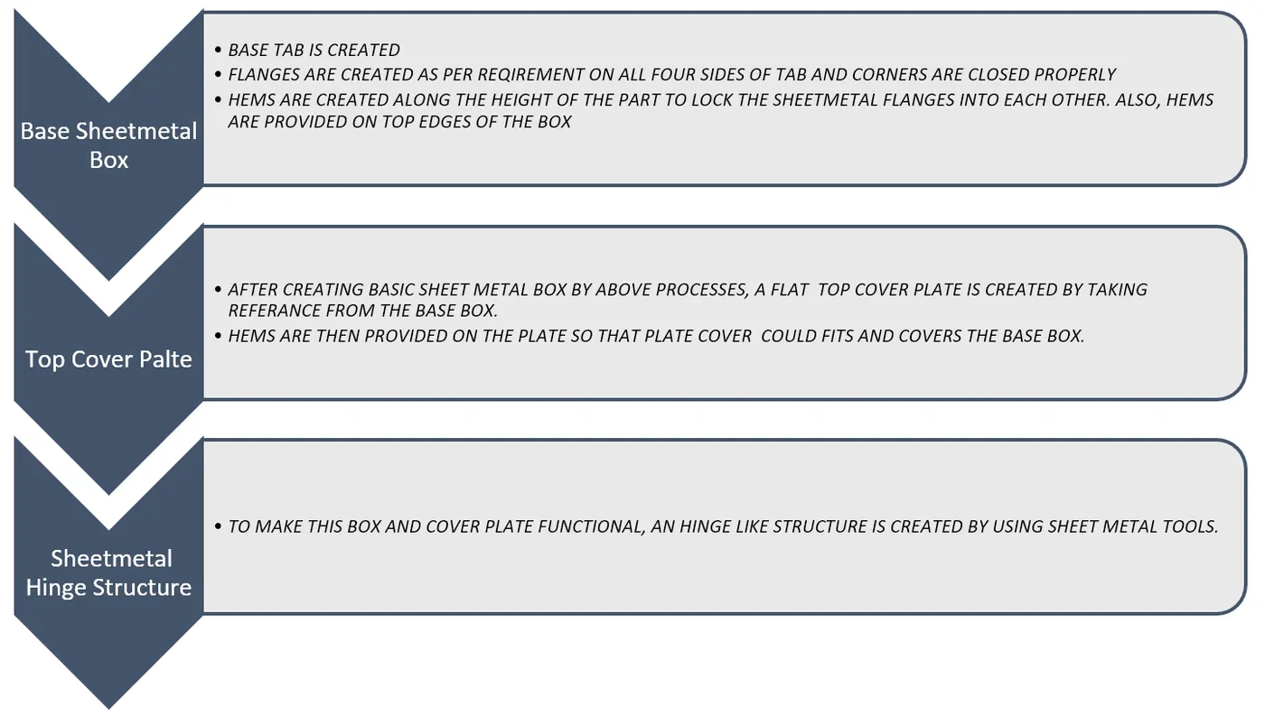
Description:-
Tools / Features used while designing the Box Assembly
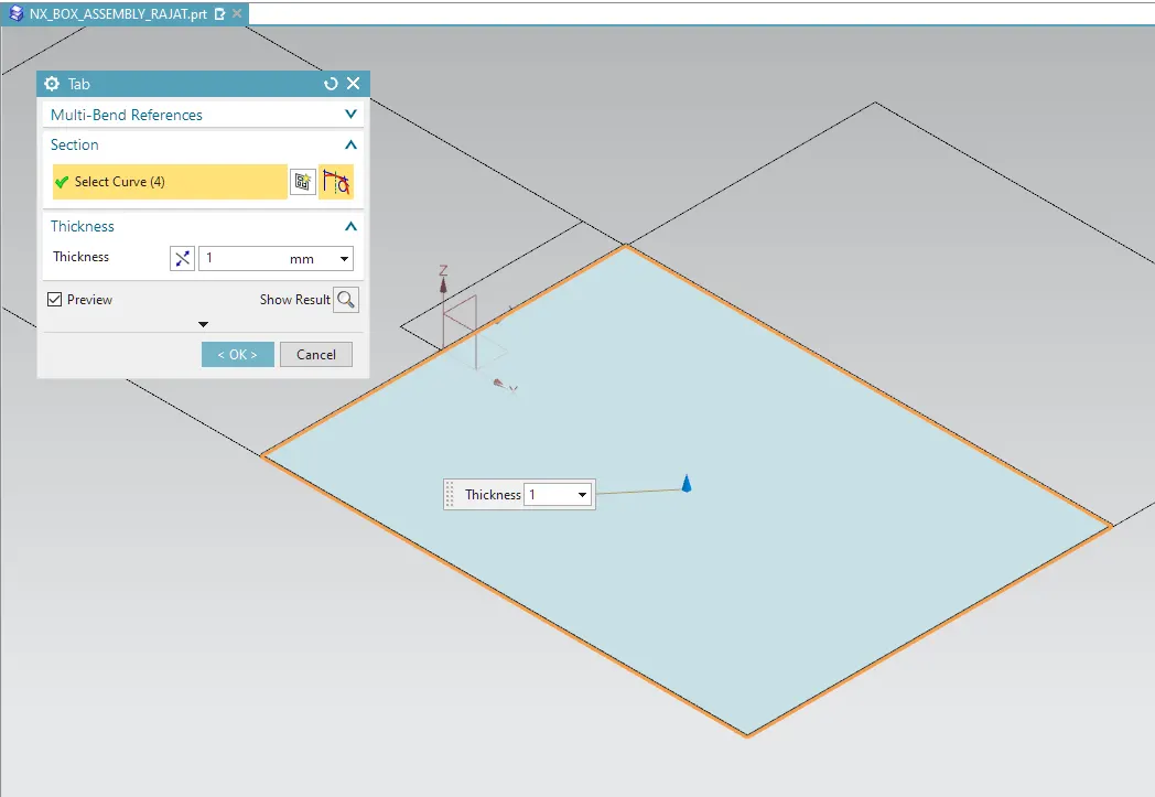
1. Tab – Tab is the basing feature in the sheet metal environment of NX-12. The tab is the initial or the startup stage of the design of the sheet metal component. By using the Tab feature we create a base for sheet metal component and decide the thickness of the sheet metal which is then followed in the further steps of design.
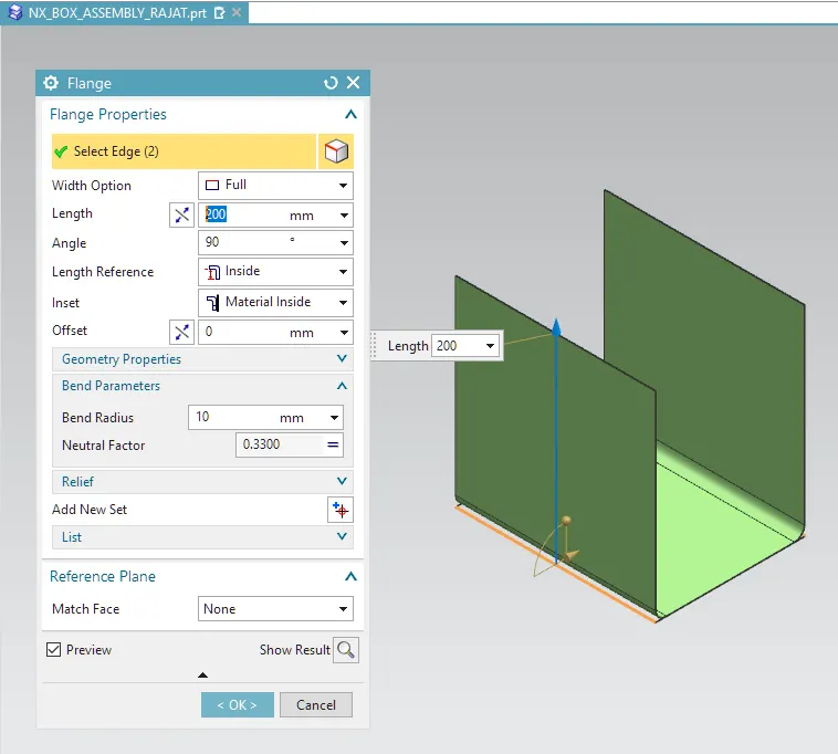
2. Flange – Flange feature is used to create an extended portion or bend to the selected edge. While creating flange we have to set different parameters such as length of the flange, its angle, length reference ( inside, outside, or web), inset ( Material inside, Material outside or bent outside). Other parameters like bend radius, bend relief, and Neutral factor is also needed to be considered.
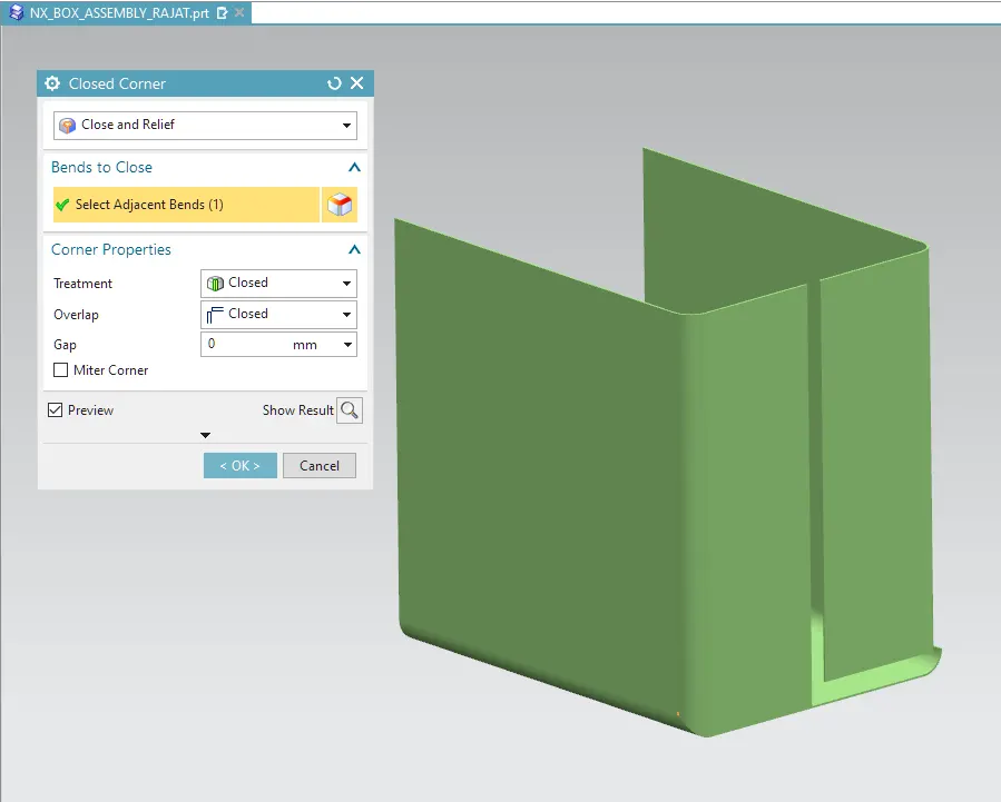
4. Closed Corner – This feature closes two adjacent flange corners in sheet metal application.
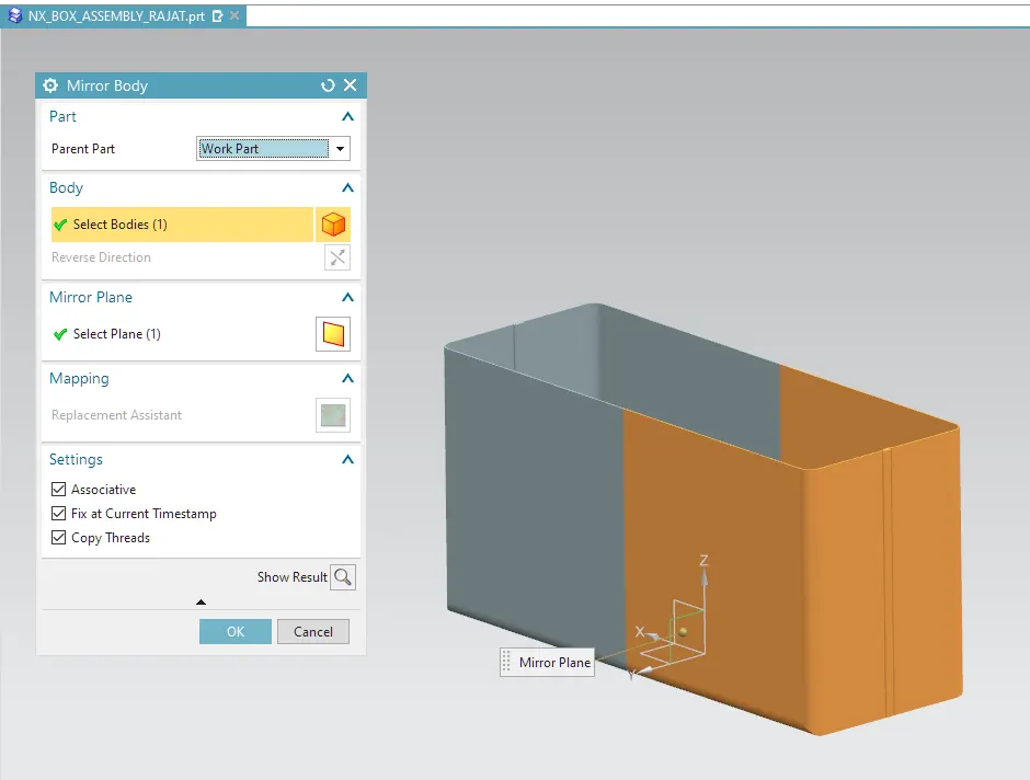
5. Mirror Body – The Mirror Body command is used to mirror an entire body across a datum plane. For example, you can use this command to form the other hand of a left hand or right-hand part.
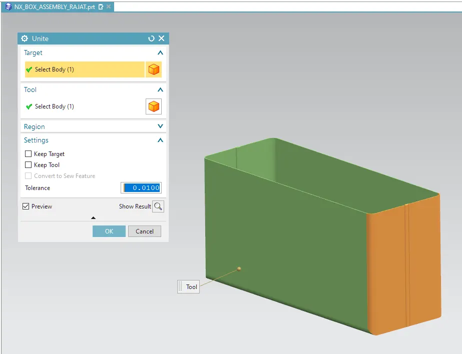
6. unite – The Unite command is used to combine the volume of two or more solid tool bodies into a single target body. The target body and tool body must overlap or share faces so that the result is a valid solid body. This command creates a Unite feature.
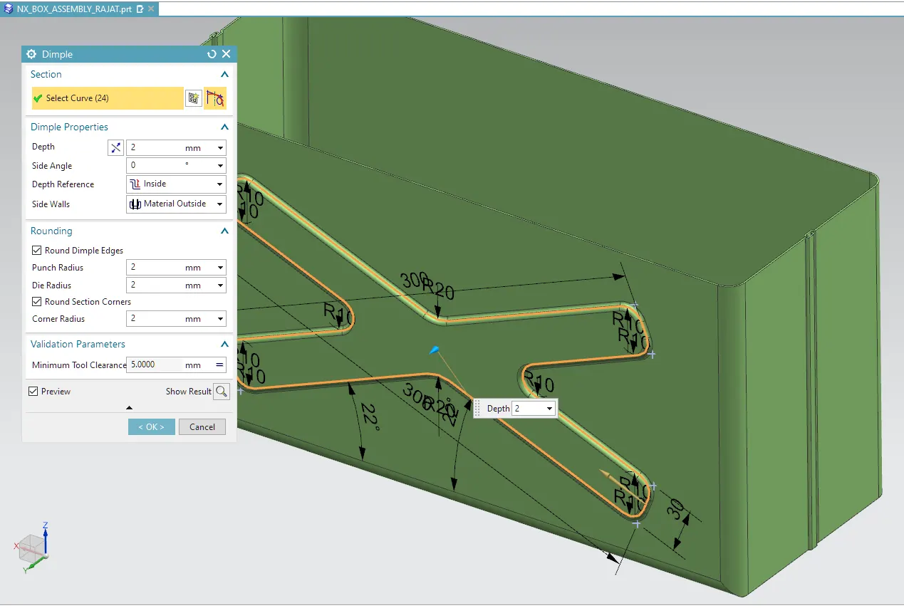
7. Dimple – This command is Use to lift an area of the model inside a sketch that simulates a stamping tool. We can create an indentation in a sheet metal part using a sketched section as the dimple outline. The Dimple command makes an indentation in the sheet metal part, using a sketched section as its outline.
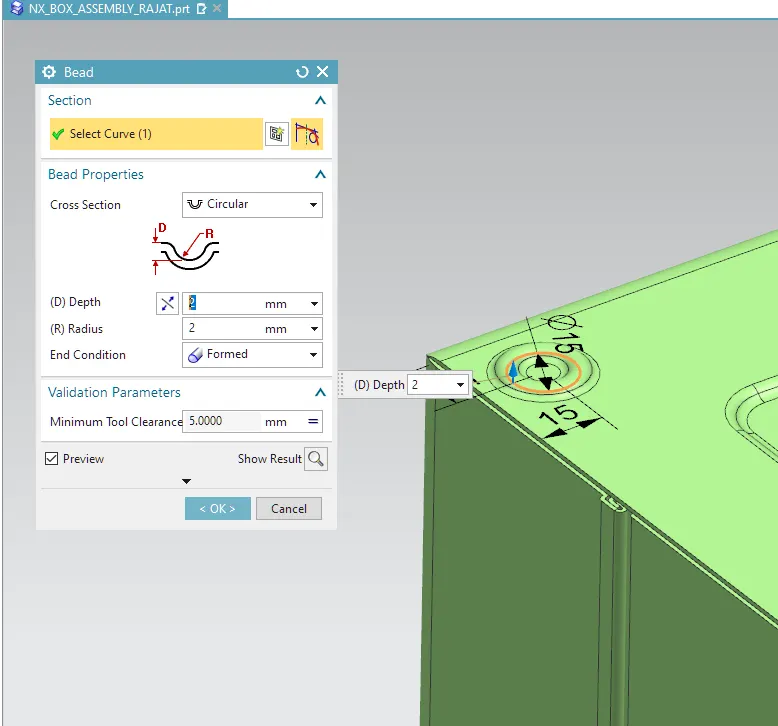
8. Bead – The bead is like a raised rib in the sheet metal panel. It requires that you have at least one sheet metal panel in the active part as well as an open or closed-loop sketch.
The Bead is another feature that has only a button for Options on the CommandBar.
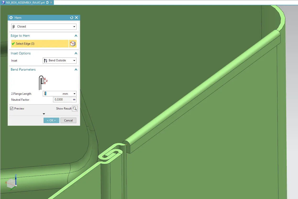
9. Hem – This command is used to modify the model or flange by folding the edge of the sheet metal flange over onto itself for the purpose of safe handling or to increase the stiffness of the flange.
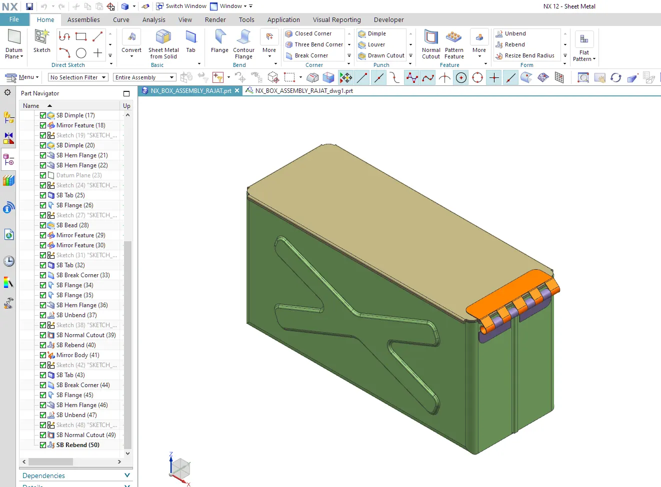
10. Rebend – Rebend feature is used to get the original bend shape after performing forming operations like a dimple, bead.
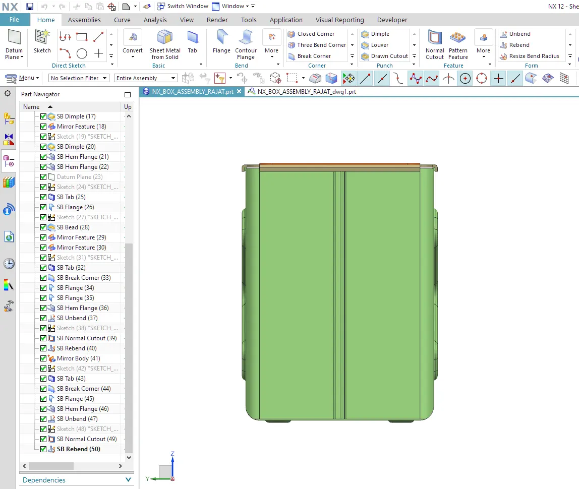
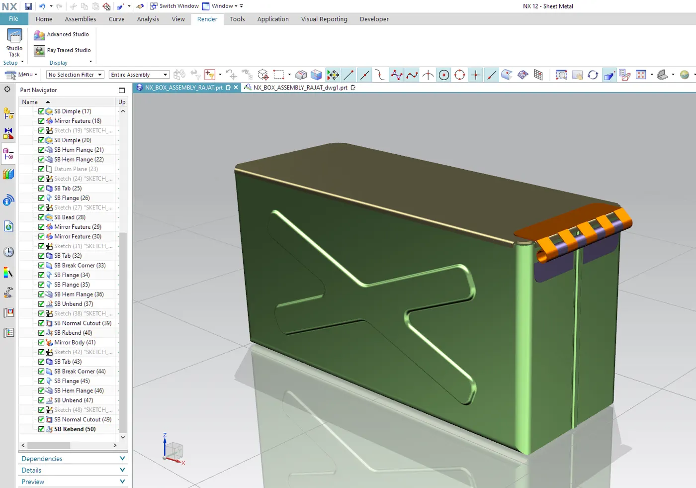
Images of Model:-
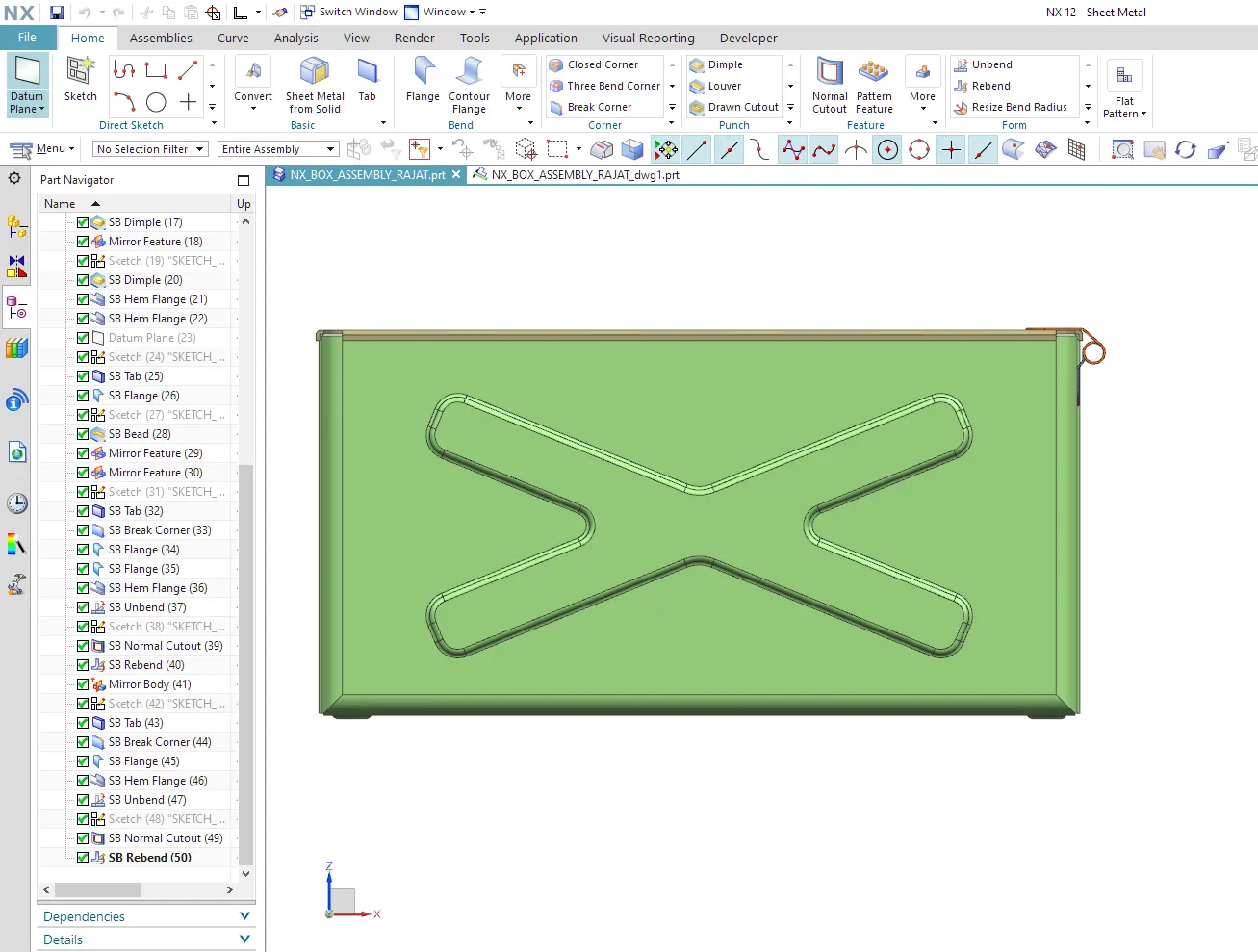
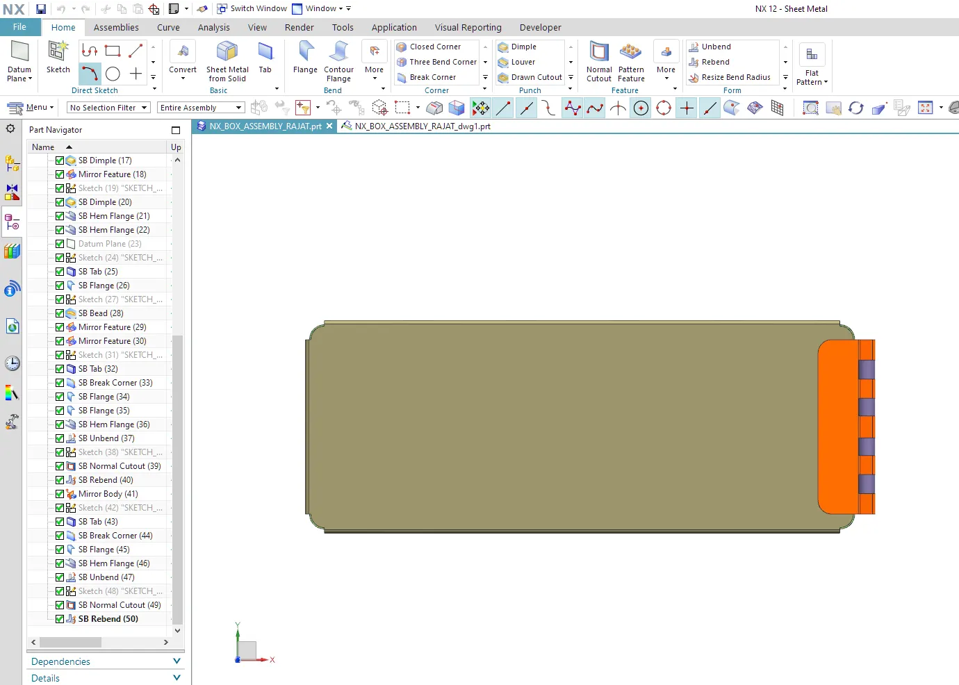
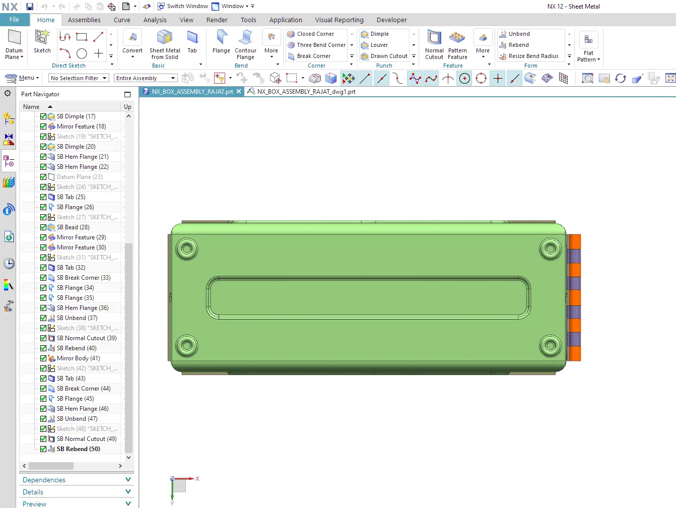
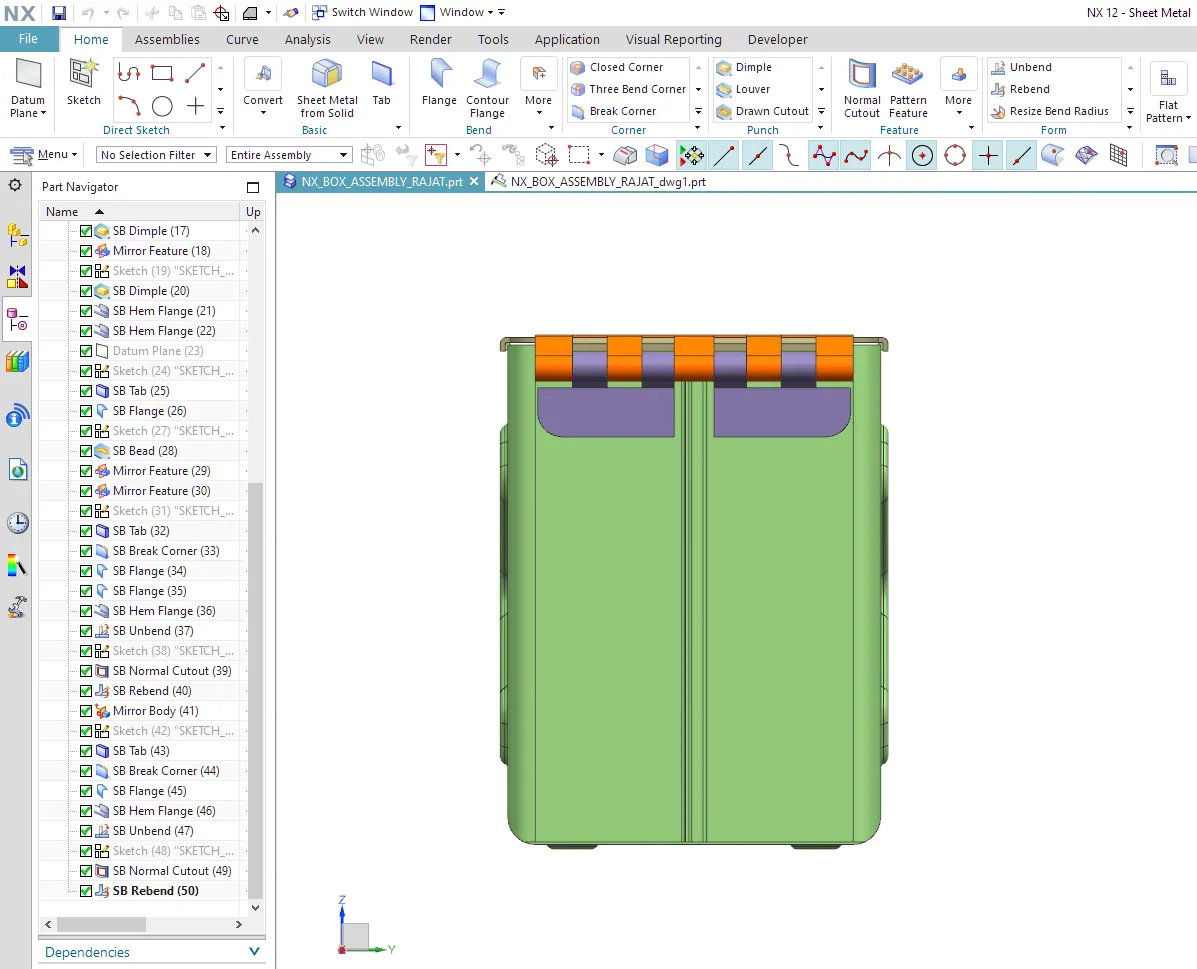
Drawing Sheet Image:-
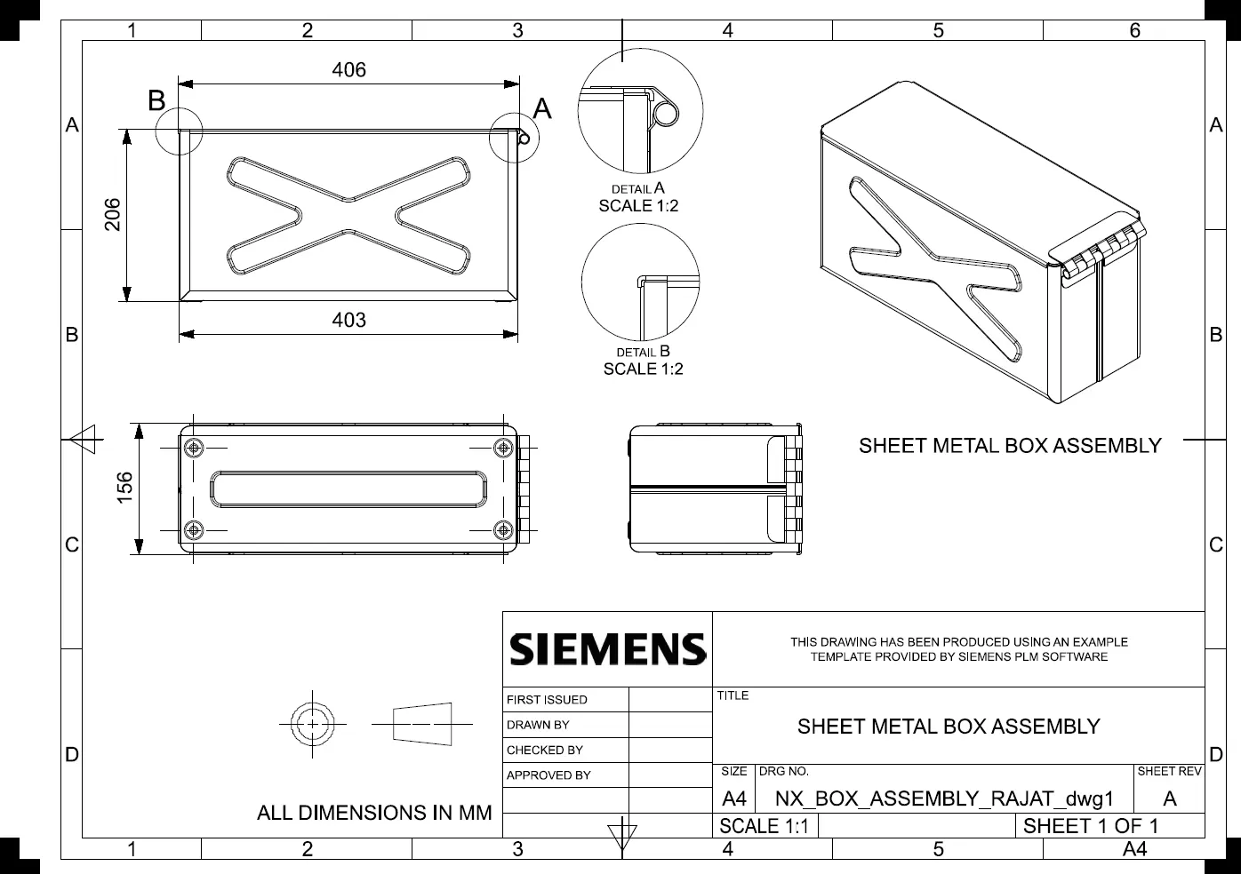
Conclusion:-
1. Sheet Metal Box Assembly is designed successfully in NX-12 Sheetmetal Environment.
2. SOme more features in the sheet metal environment pf NX-12 like the closed corner, mirror body, unite body, hem are learned and mastered.