Advanced Sheet Metal Design Using NX Cad Challenge_2_Box Assembly
Box Assembly
Objective -
To Design a Sheet metal box assembly using NX sheet metal workbench
Introduction -
Sheet metal is a metal forming process through industrial process into thin, flat pieces. Here, I have created a Sheet Metal Box assembly of Various thickened parts. Box assembly contains 3 main parts.
- Box (base part)
- Box Lid
- Hinge
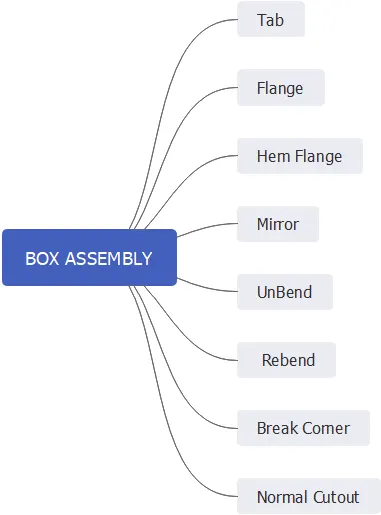
To design this parts I have used NX sheet metal workbench. Design methodology I have used to design this is described below.
Design Methodology:
Description -
Step by step process of constructing cad model of Box assembly desribed here. Tools used to construct cad model also described here.
THis box assembly has 3 parts hence, I have described these process according to these 3 parts
- Box
- Box lid
- Hinge
- Box
1) Sketch :
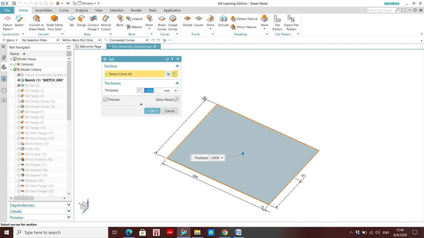
200mm x 150mm sized rectangle created on the XY plane of datum coordinate system
2) Tab:
Base of the box created using sketch drawn in XY plane
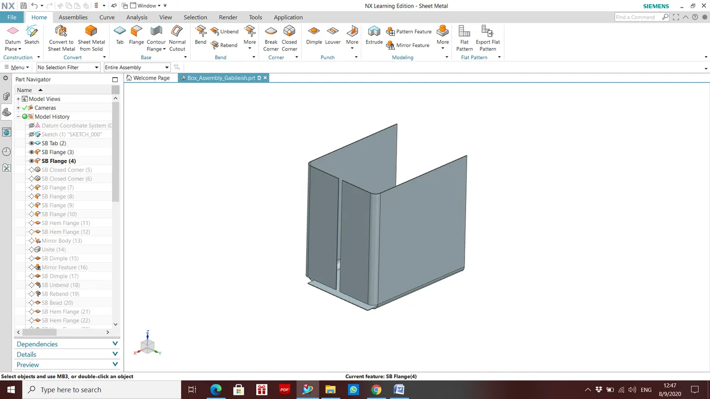
3) Side Flanges:
Side walls of the Box created using flange option
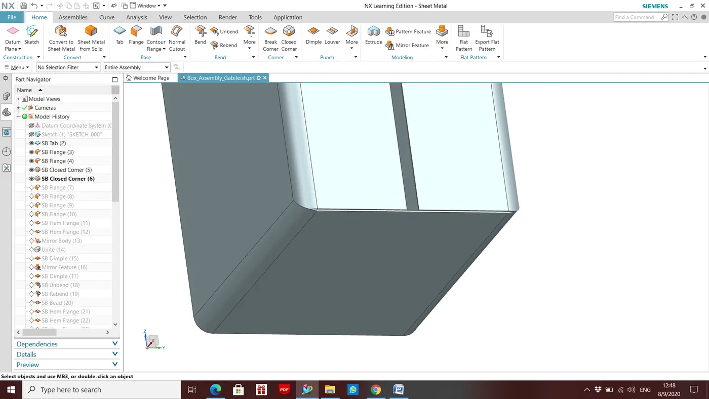
4) Closed corner:
This tools used to Provide smooth corner by removing intersection, handling gap and smoothning ends of the flanges
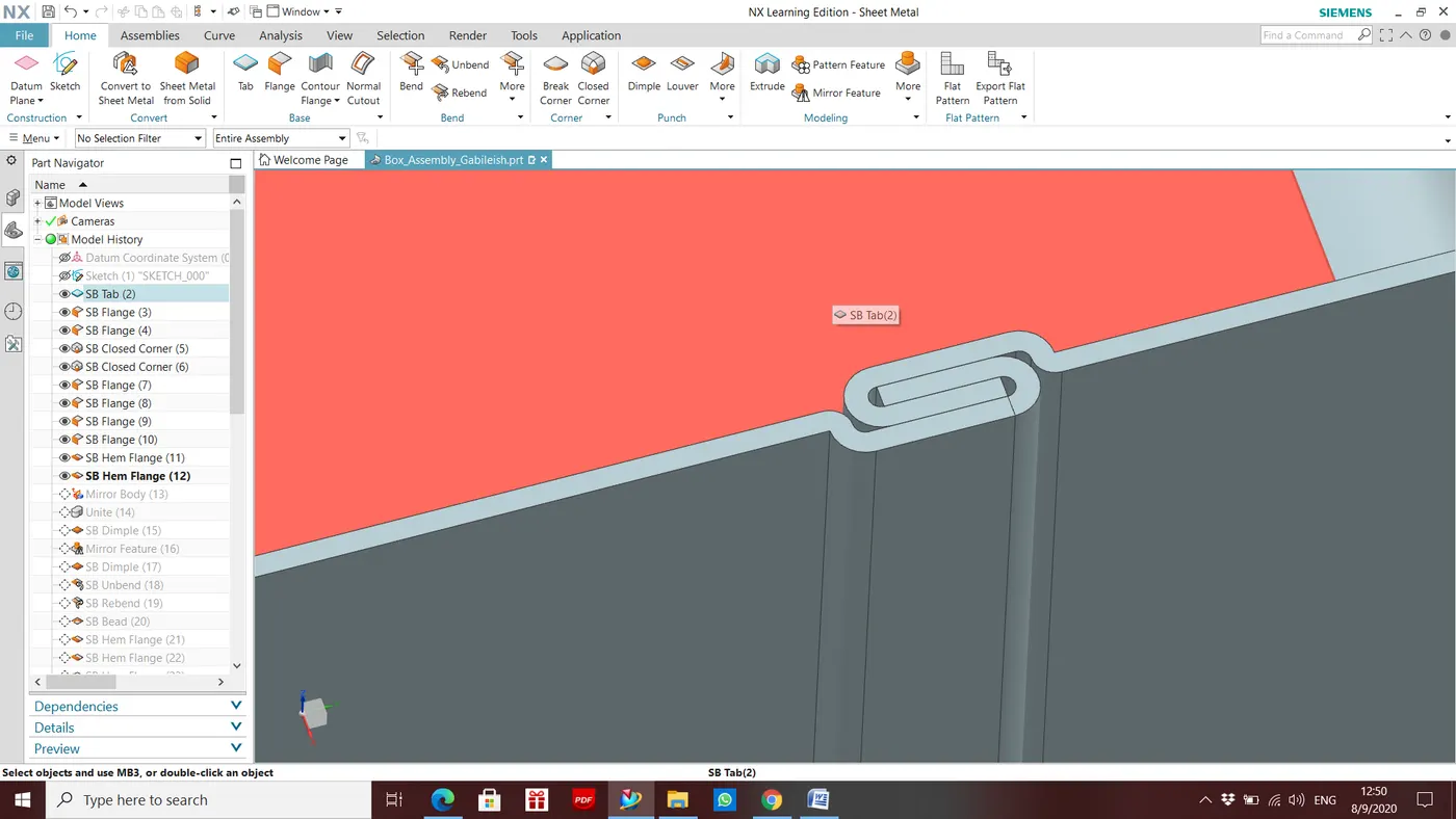
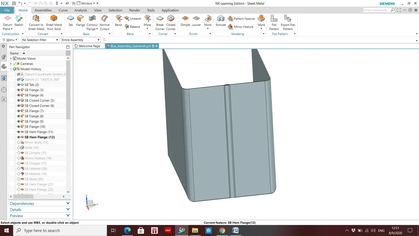
5) Hem Flange:
Close loop of Hem flange created at the open ends of the side walls to close the gap between flanges of side walls.
6) Mirror Body
Body of the box completed by mirroring body.
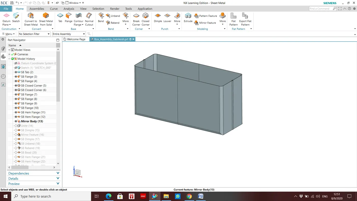
6) Unite
After using mirror body tool 2 saperate body created. This tool united those saperated bodies.
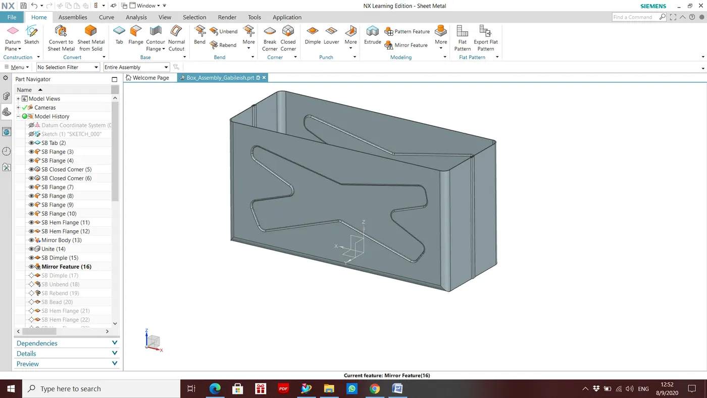
7) Dimple
Embosses created on the body of the box to increase strength. Dimple tool used to create embosses..
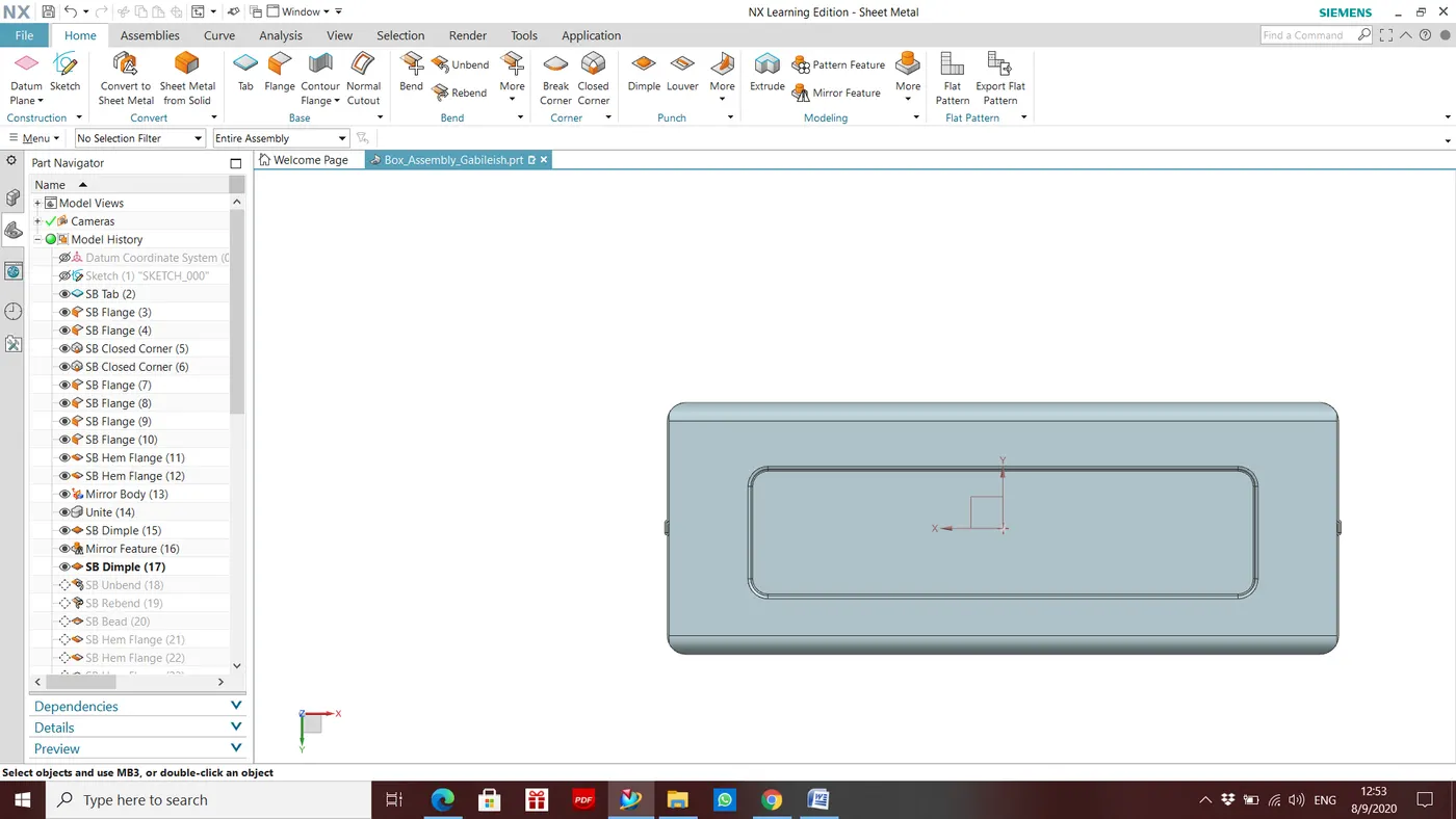
8) Bead
Bead created on the bottom of the box, sketch drawn for the bead attached below.
- Box Lid
1) Datum plane
Datum plane w.r.t. XY plane of datum coordinte system to an offset of 203mm created.
2) Sketch
I have created sketch on the above created datum plane as a reference for Box lid
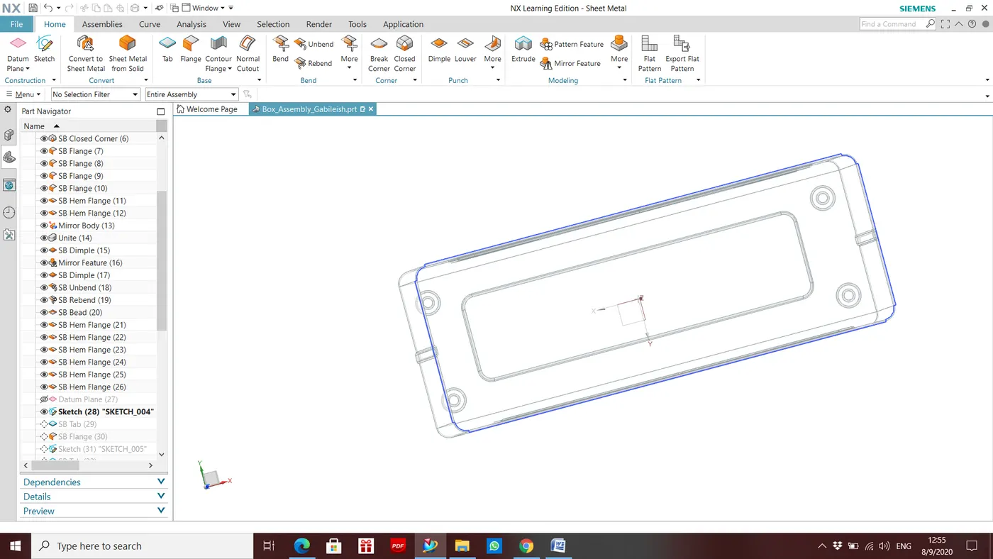
3) Tab
Box Lid created using Tab tool
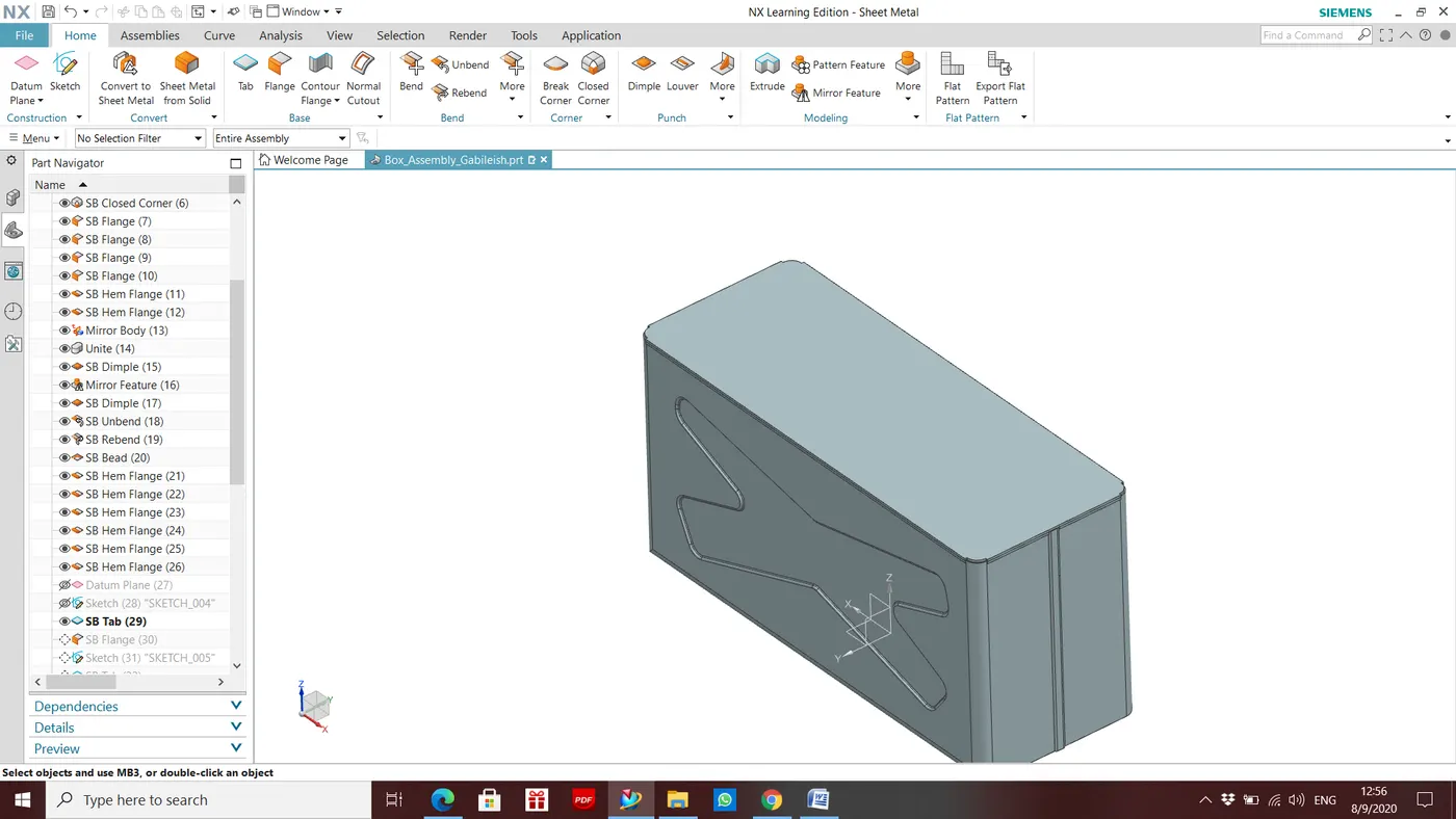
- Hinge
Here, Hinge created in 2 parts
- Box Part
- Box lid part
1) Tab
Base flange of the Hinge box part created using flange tools. Sketch created as on the side wall of the box.
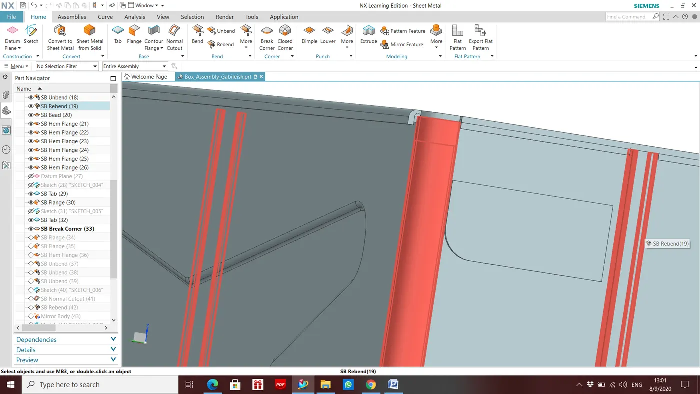
2) Break Corner
Corner blended with keeping 10mm radius
3) Flange
02 additional flanges created on w.r.t. base flange created above.
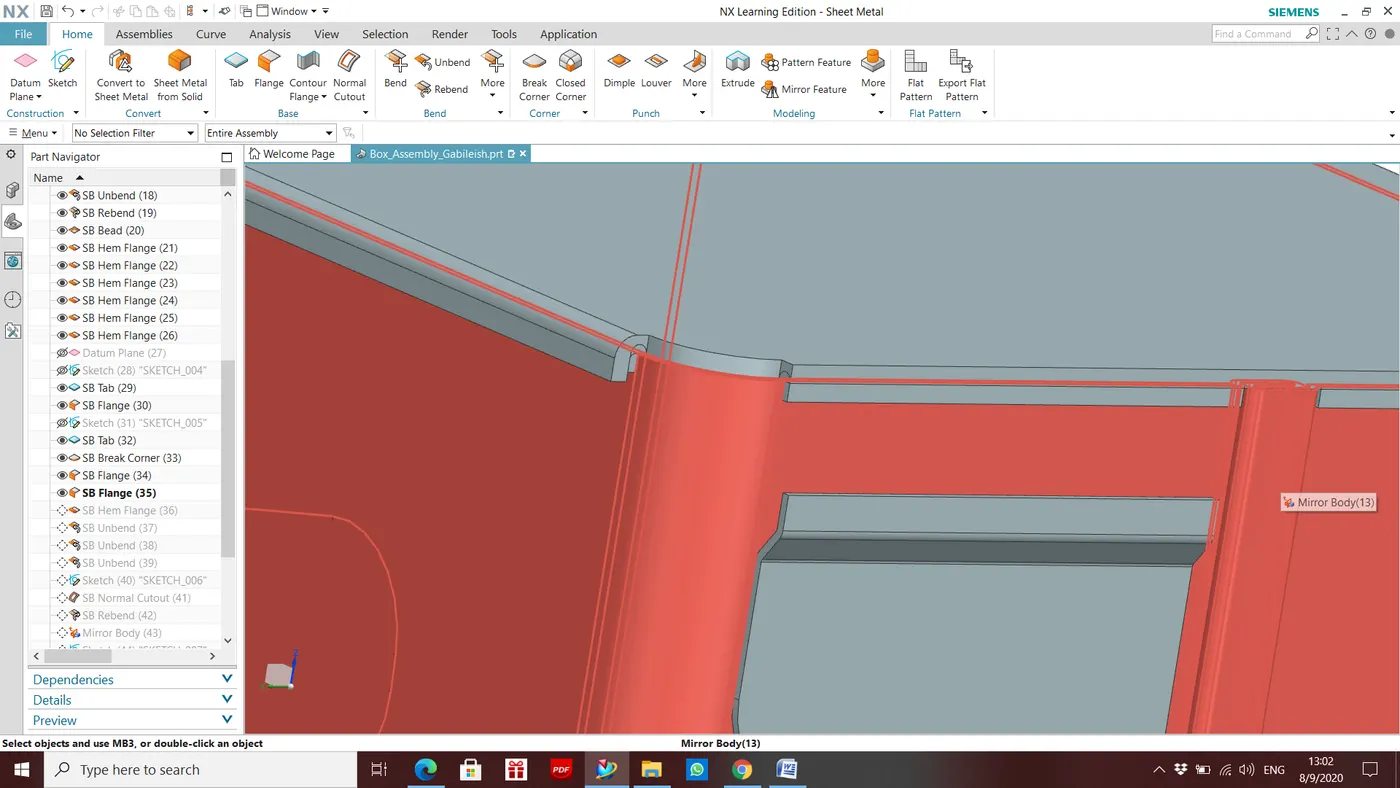
4) Hem Flange
Open loop of hem flange created
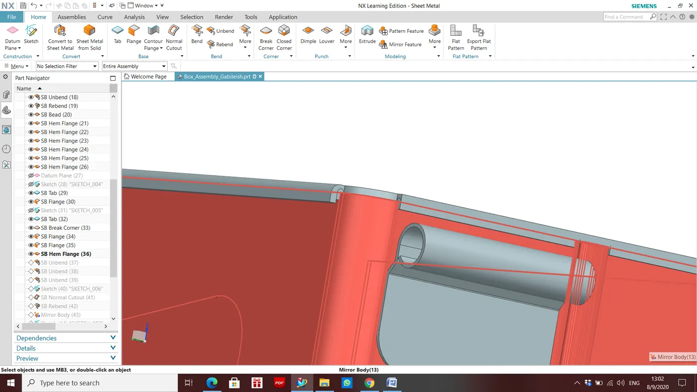
5) Unbend, Normal Cutout & Rebend
Flattened Hinge portion to perform normal cutout and than rebend to get hinge in it's original position
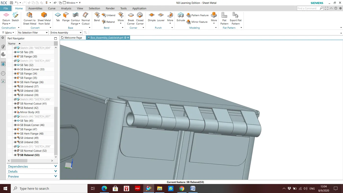
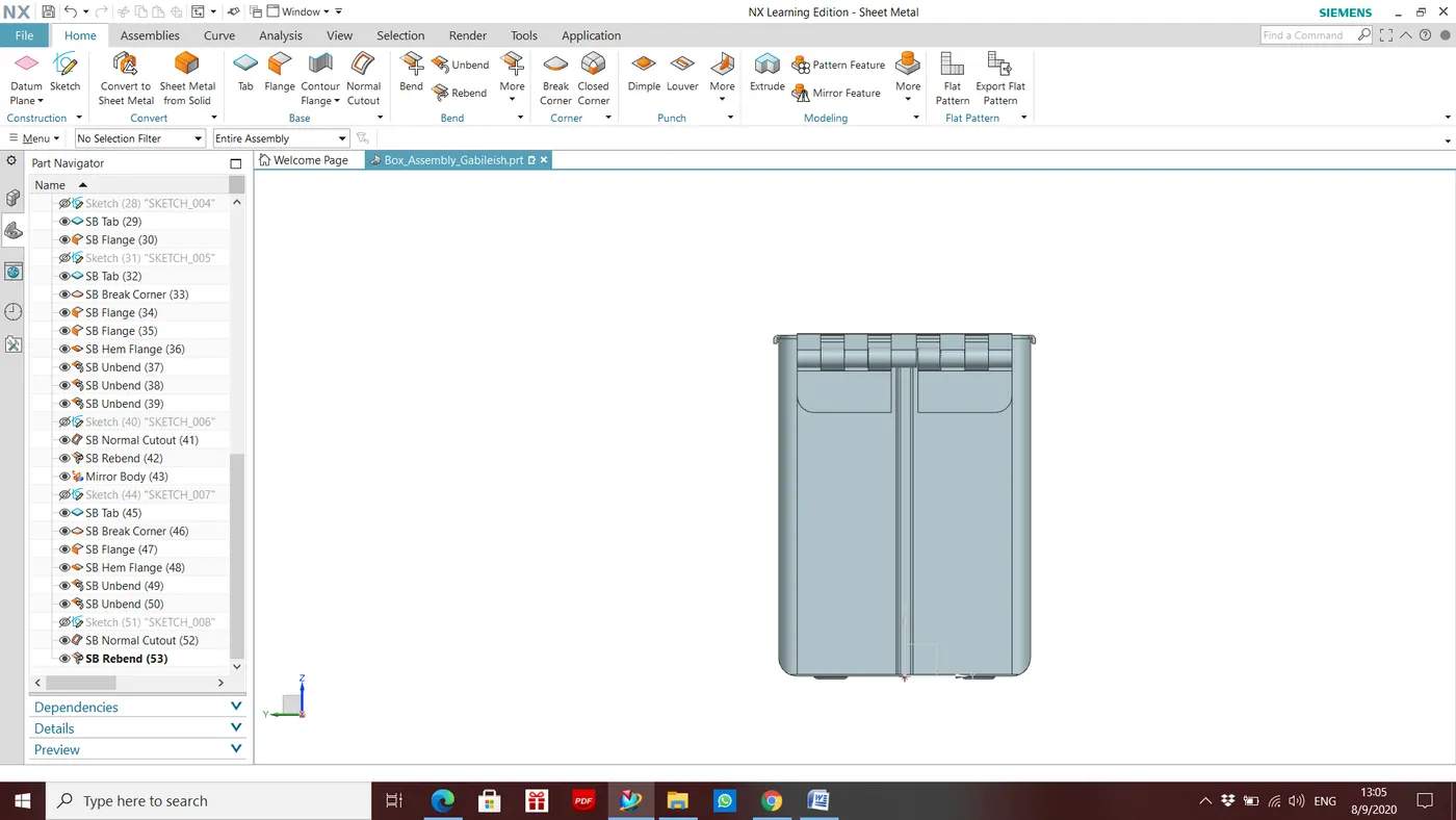
FRONT VIEW:
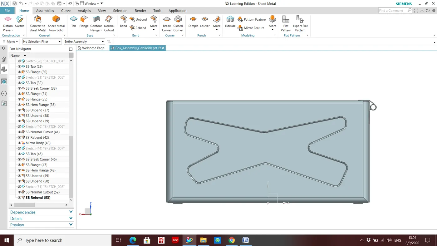
SIDE VIEW:
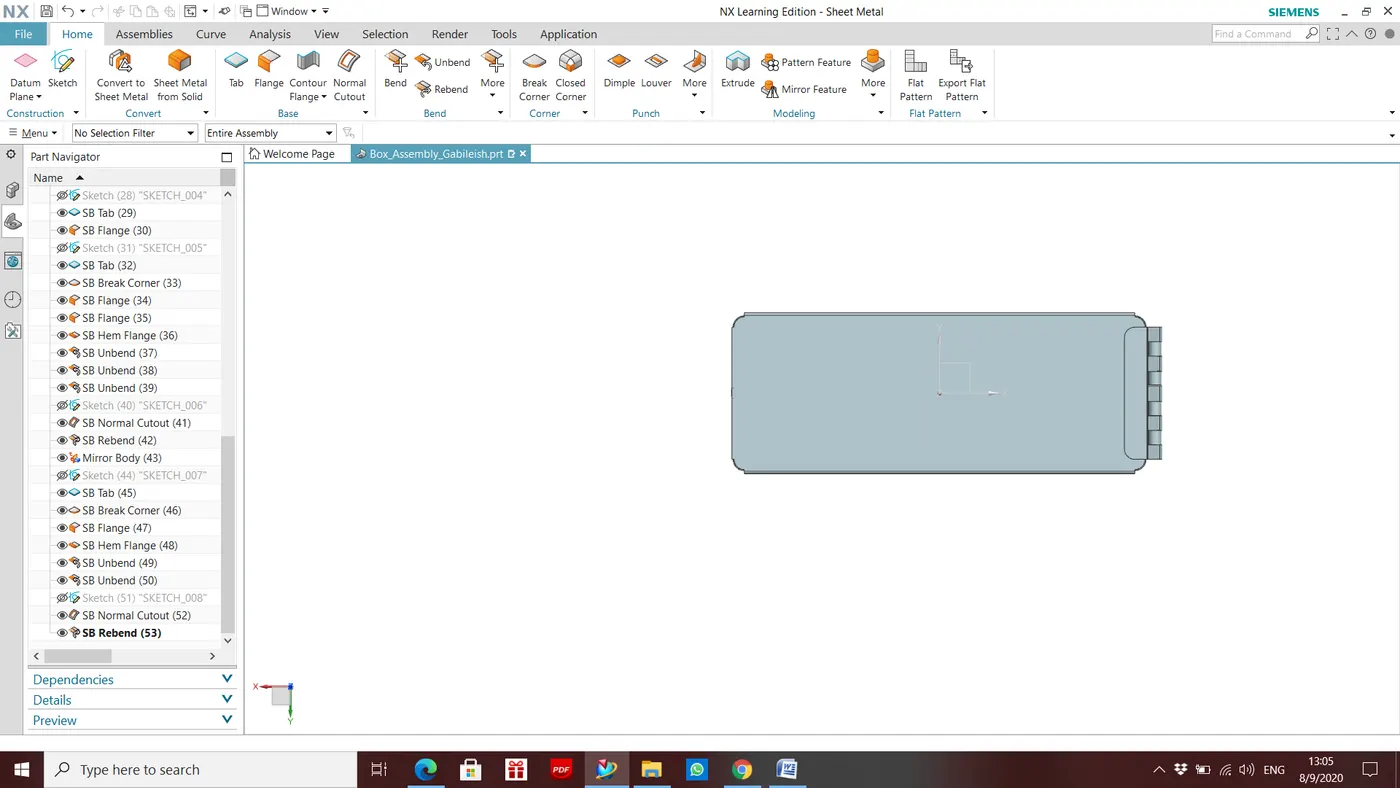
TOP VIEW:
ISOMETRIC VIEW: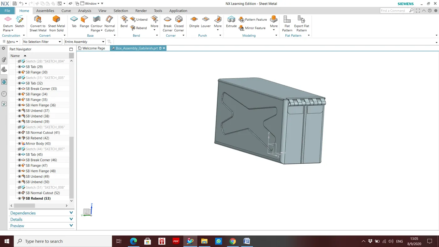
Conclusion -
By doing this project I have learned some new NX sheet metal work bench tools like Hem flange, Closed corner. Understood the Design Methodology to create this type of sheet metal parts.