Advanced Sheet Metal Design Using NX Cad Challenge_2_Box Assembly
Box Assembly Design using Sheet Metal in NX CAD:
Objectives:
- To explain the Sheet Metal features and tools used to create the Box Assembly in NX CAD
- To create a Box Assembly using Sheet Metal in NX CAD
- To create a Drawing of the Box Assembly in NX CAD
Introduction:
Sheet Metal: is a term used to refer to any metal with variable thickness, which can be bent and formed into complex shapes. Although having low weight to volume ratio, sheet metals have more strength and durability than plastics and other materials. They provide great applications in industries such as automotive, aerospace, defence, construction, consumer products, among others.
NX CAD: formerly known as NX Unigraphics, is a CAD/CAM/CAE software owned by Siemens Industries Software Inc., since 2007. It is a highly versatile software, especially for product development, wherein it finds its uses right from designing the product, to simulation studies, and even provides manufacturing solutions. Here, the Student Version of NX CAD is utilized for undertaking Sheet Metal Design.
The following Sheet Metal Features and Tools from NX CAD are used to design Box Assembly:
- Tab - is used to create a base solid by extruding a sketch along a vector by a thickness value.
- Flange - is used to add a flat flange at an angle to a planar face and adds a bend between the two.
- Closed Corner - is used to close a corner where two adjacent flanges meet by extending the bends and flanges.
- Hem - is used to fold the edge of a sheet metal flange over onto itself for the purpose of safe handling or to increase the edge stiffness.
- Mirror Body - is used to copy a body and mirror it across a plane.
- Unite - combines the volume of two or more solids into a single body.
- Dimple - is used to lift an area of a model inside a sketch that simulates a stamping tool.
- Mirror Feature - is used to copy a feature and mirror it across a plane.
- Unbend - is used to flatten a bend and the material adjacent to the bend.
- Rebend - is used to restore an unbend feature to its previous bent state, along with any features added after the unbend feature.
- Bead - is used to lift an area of a model inside a sketch that simulates a stamping tool.
- Datum Plane - is used to create a datum plane to construct other features.
- Break Corner - is used to round or chamfer sharp corners of a tab or flange.
- Normal Cutout - is used to remove material by projecting a sketch onto a solid and then cutting perpendicular to the faces intersected by that projection.
Design Methodology:
The usual approach for a Sheet Metal Design is as follows:
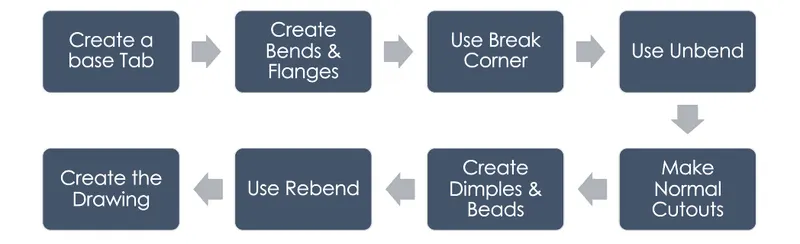
Description:
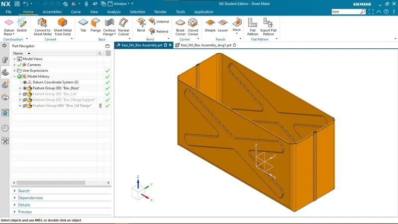
- Create the Base
- Create the bottom of the Base using Tab command on a base Sketch
- Create the side walls using Flange and Closed Corner commands.
- Create the interlocking side walls using Flange and Hem Features.
- Mirror the body to create a complete Base.
- Use Unite command to join the halves together.
- Create projections on the side walls of the base using Dimple and Mirror Feature commands.
- Finish the Base with the Hem features along the brim.
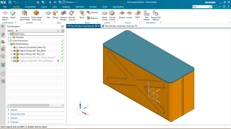
- Create the Lid
- Create a Datum Plane at desired orientation and create a Sketch.
- Create a Tab using the sketch.
- Create Flanges on all sides.
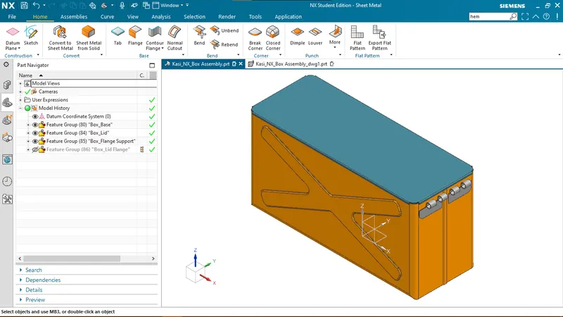
- Create the Flange Support
- Use Tab command on a new sketch on the side wall.
- Round the corner of the Flange support using Break Corner command.
- Create the basic shape of the Flange support using Flange and Hem commands.
- Use Unbend command to straighten out the Flange Support.
- Create a sketch on the unbent Flange Support.
- Use Normal Cutout command on the sketch to remove material from the flange support.
- Use Rebend command on all the faces to complete the Flange Support.
- Create the Lid Flange
- Create a Sketch on the top face of the Lid.
- Use Tab command on the sketch.
- Round the corners using Break Corner command.
- Create the basic shape of the Lid Flange using Flange and Hem commands.
- Use Unbend command to straighten out the Lid Flange.
- Create a sketch on the unbent Lid Flange.
- Use Normal Cutout command on the sketch to remove material from the Lid Flange.
- Use Rebend command on all the faces to complete the Lid Flange.
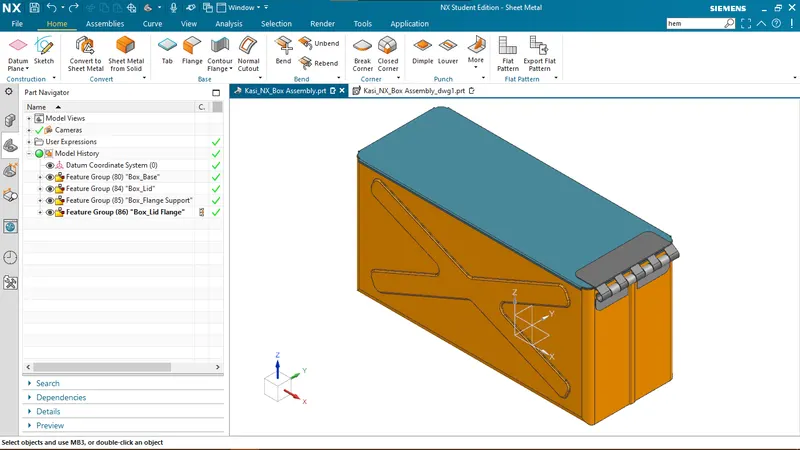
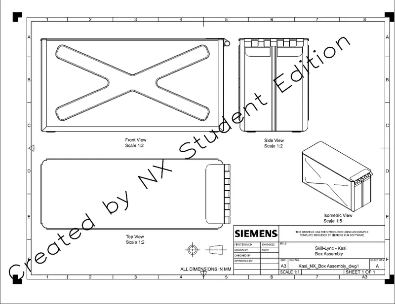
Images of the Box Assembly:
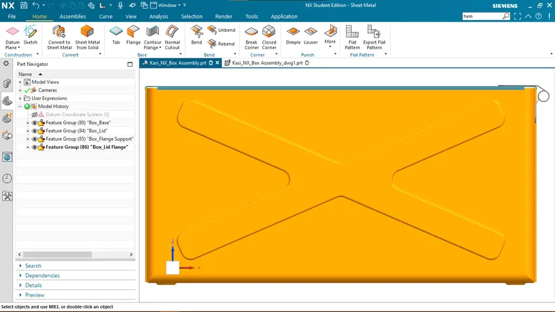
- Front View
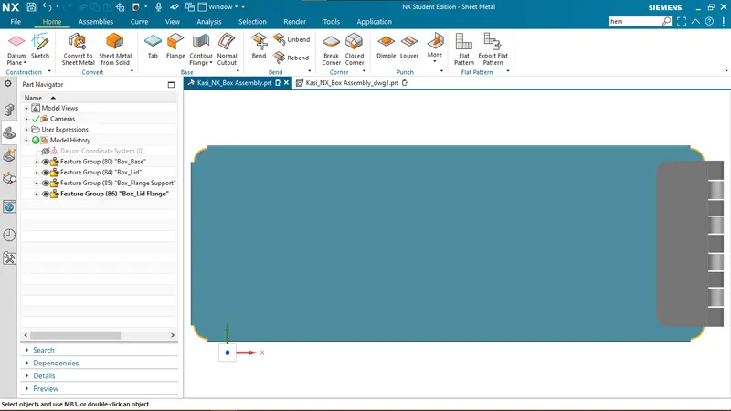
- Top View
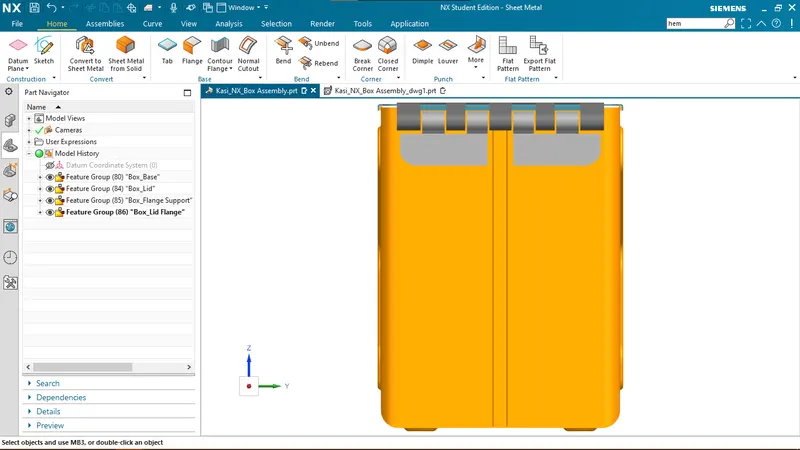
- Side View
- Isometric View
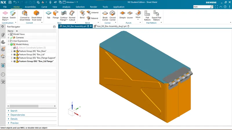
Drawing of the Box Assembly:
Conclusion:
- Hence, the Sheet Metal features and tools in NX CAD are explained.
- A Sheet Metal Box Assembly is designed using Sheet Metal Features in NX CAD.
- A Drawing of the Box Assembly is created in NX CAD.