Advanced Sheet Metal Design Using NX Cad Challenge_2_Box Assembly
MODELLING OF BOX ASSEMBLY
OBJECTIVE: This project aims to design the box assembly using sheet metal modelling in the NX cad sheet metal workbench.
INTRODUCTION: The present project to develop a box assembly using NX Cad requires convenient designing along with subsequent operations to perform to get the desired assembly. The following operations are performed on the casing are as follows:
- Tab
- Flange
- Closed corner
- Hem flange
- Mirror body/feature
- Unite
- Dimple
- Unbend
- Rebend
- Bead
- Datum Plane
- Break corner
- Normal Cutout
DESIGN METHODOLOGY: The flow chart resembles the sequence in which the process follows:
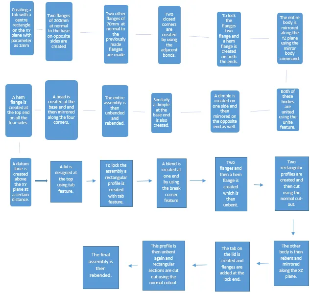
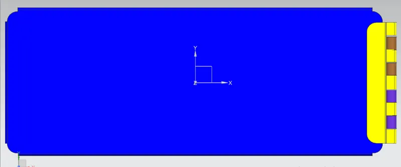
DESCRIPTION: The box assembly is designed with subsequent operations that use various features described as follows along with the flow with which we design the entire assembly. After sketching the XY plane it is extruded using the tab command with global parameters of 1mm.
Tab- This feature is used to extrude a thin surface of applied thickness by extruding along a certain direction and the sketch is usually a closed path.
After this two flanges normal to XY plane are created at a length of 200mm and then two flanges normal to XZ plane are created.
Flange- When one needs to add a flange along a reference edge using the reference face, this command is used.
After this, relief is added at the adjacent bends by using the closed corner feature.
Closed corner- When in any sheet metal if corners are opened and needed to be added relief, to close two adjacent flanges this command is used.
After this flanges are added at the open end to close the profile. The entire body is then mirrored along the YZ plane using the mirror body feature. After this, the two separate bodies are combined using the unite command. Dimple on one side and at the bottom end is made with the help of a reference sketch.
Dimple- This feature is used to emboss a certain profile over the sheet metal by using the sketch reference up to a certain depth similar to punch. This similar profile is then mirrored along the XZ plane for the other side.
A bead is added at the bottom end with a circular profile and then is mirrored along the YZ plane and then these two features are then again mirrored along the XZ plane.
Beads- The beads are also similar to the punching operation which embossed the sketch on the sheet metal part. The circle made is punched up to a certain depth.
A hem flange is added at the top end side to interlock on the three sides. A datum plane is then added at a certain distance from the XY plane. A lid is then made on the plane and extruded using a tab feature. After this, the flanges are added at all four ends of the lid. To lock the lid and base a sketch is created at one end and is extruded using the tab command. Some extra flanges are added and this profile is unbent to get a cut-out.
Unbend- To unbent back the bent sheet a stationary face along with the stationary edge is used and the adjacent face is then unbent. This operation is applied in proper order until the desired result is obtained.
Normal Cut-out- This feature takes out the sheet metal section from the extruded part and is used to extract a surface from the previously created tab.
This entire feature is then rebent using the rebend command and then mirrored along the ZX plane.
Rebend- Similar to selecting the reference edge and the stationary face this command is used to get back the result.
After this, a profile is added on the lid side to interlock the base and the lid. Moreover, flanges are added to this tab feature and unbent to create a normal cut-out and then rebent.
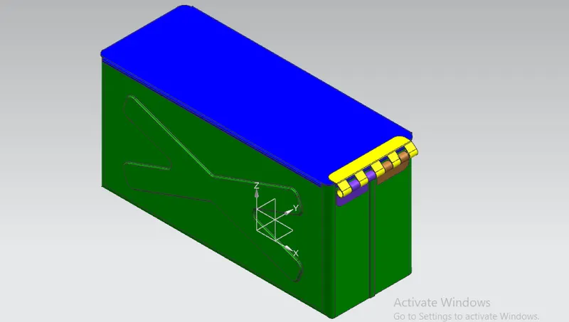
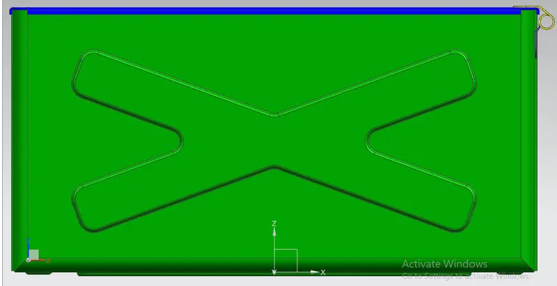
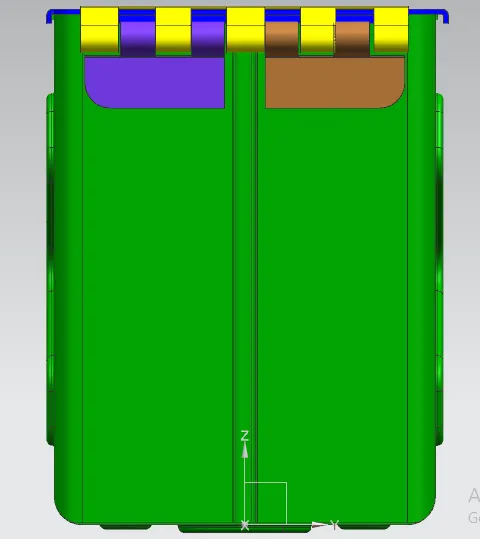
CONCLUSION: Hence the design of box assembly is done successfully.