Advanced Sheet Metal Design Using NX Cad Challenge_2_Box Assembly
Points to be followed in report
Title of the Project
Objective
Introduction
Design methodology / approach (To be explained with the help of Flowcharts only)
Description (Need to explain tools/ Features used while designing)
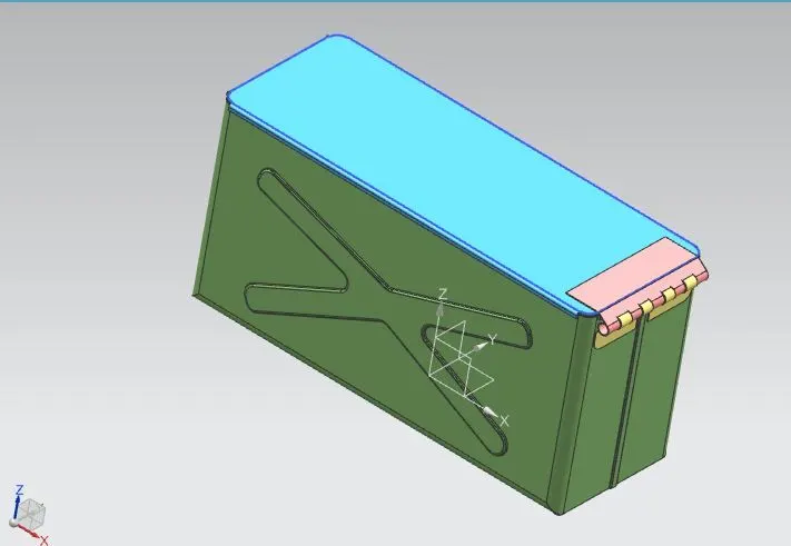
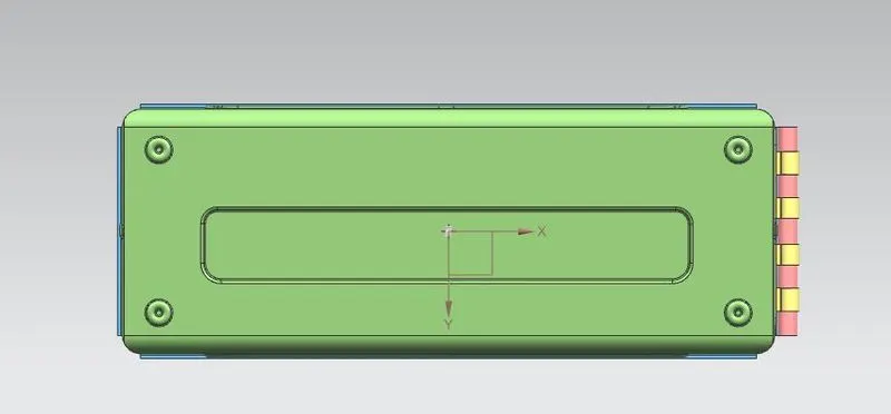
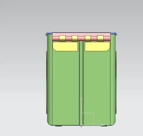
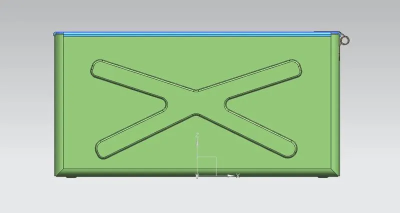
Upload a min of four screenshots of Model in the report. (Front View, Side View, Isometric View and the Top View)
Attach Detailed Drawing Sheet Image (If Required)
Conclusion
TITLE OF THE PROJECT: Box Assembly
OBJECTIVE: To model the Box Assembly in NX CAD Sheet metal with required output and submit a report
DESIGN METHODOLOGY
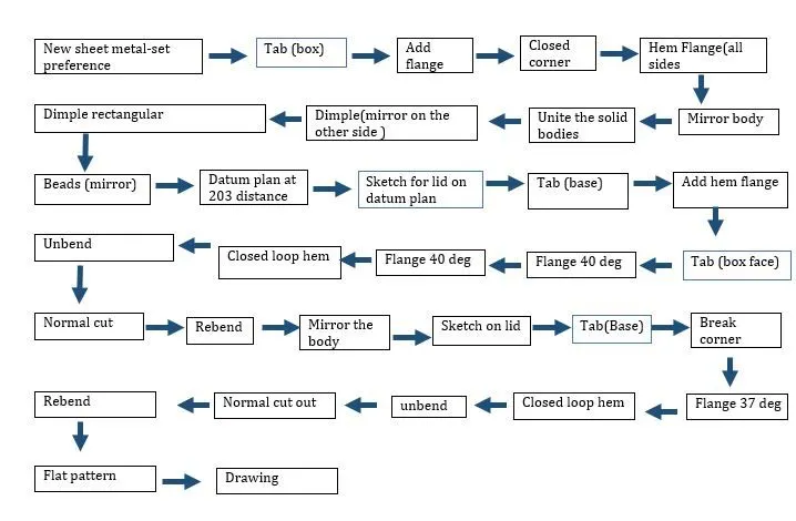
DESCRIPTION
New sheet metal page is opened and the sheet metal preferences are set.
the box assembly consits of 4 body box,Lid and the connecter(2)
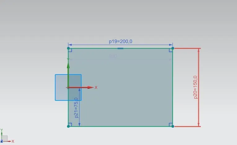
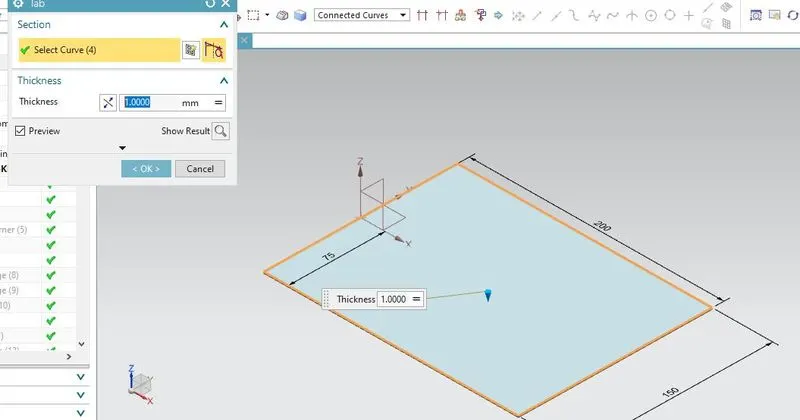
starsting with the box.Draw a sketch in XY plane of rectangle 150x200mm finish the sketch .Tab for 1mm thickness.
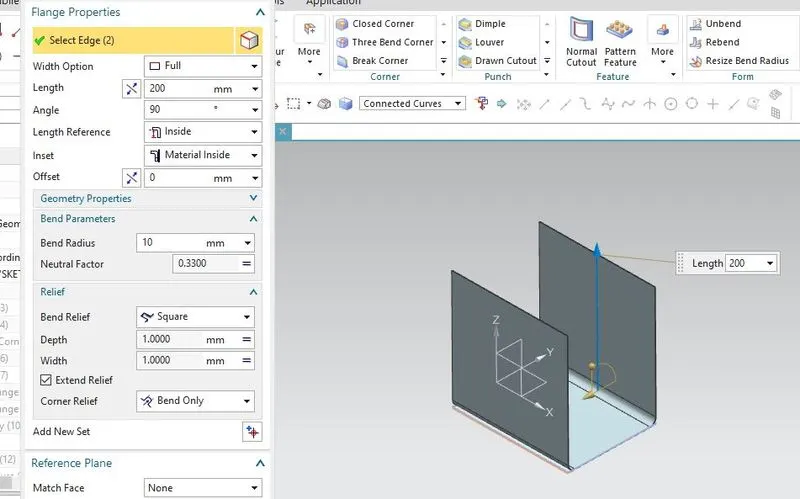
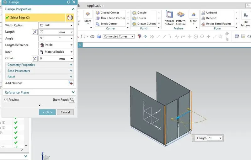
flange normal to xy plane ,in the length of rectangle side.Flange length of 200mm and bend radius 10 is given.on the other side at 70mm length
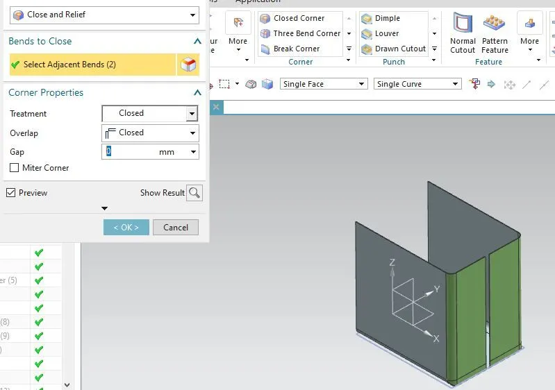
give closed corner at the bottom using adjacent bends.
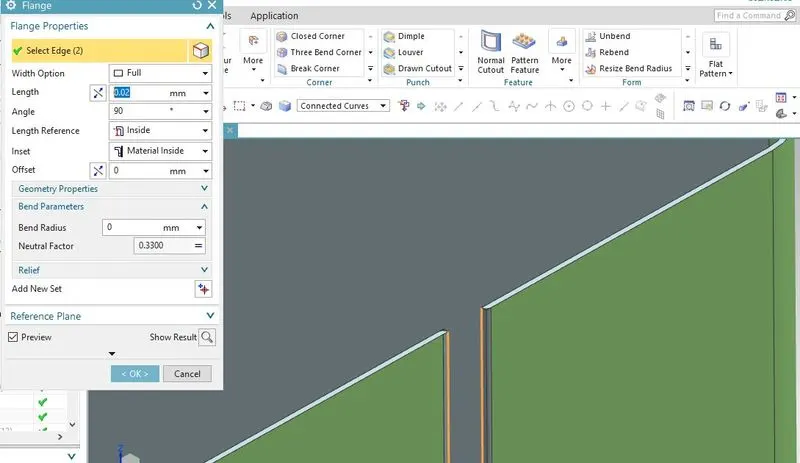
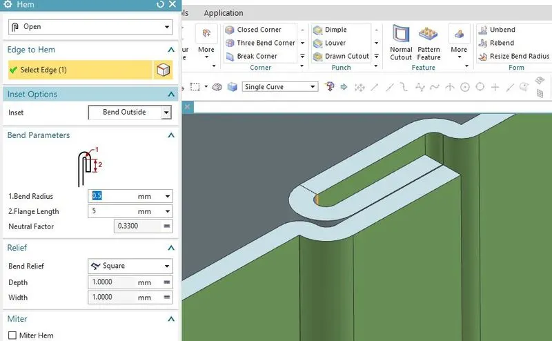
Flange with 0 bend radius is given onthe 70mm flange edge.Then hem flange with open type and bend radius of 0.5 is given.
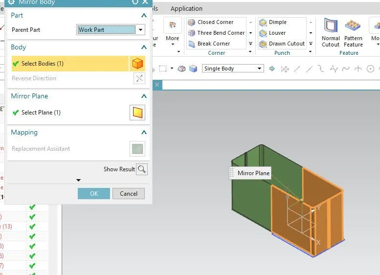
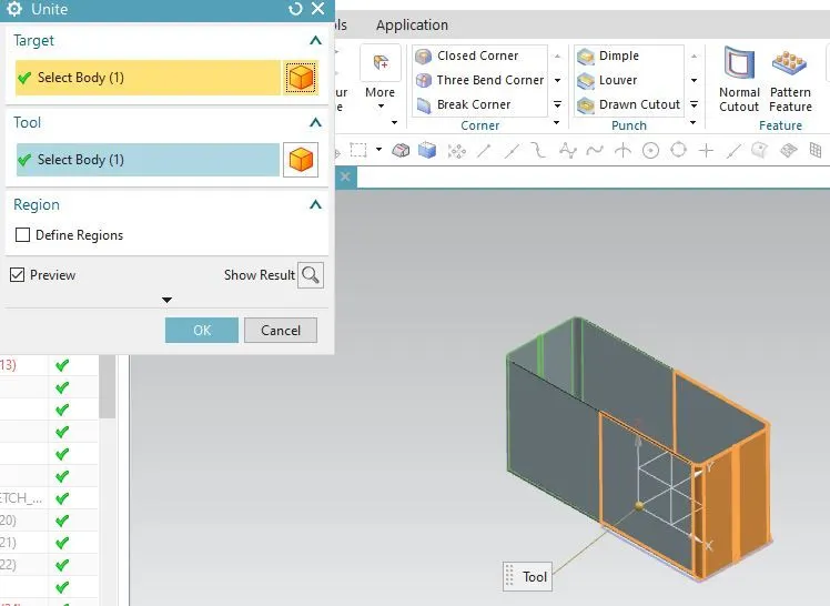
the solid body is mirrored and both bodies are united.
sketch is drawn on the vertical face with radius 10mm for Dimple.The feature is mirrored on the other side.Again on the horizontal face a rectangle is drawn click on dimple
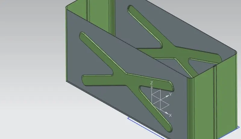
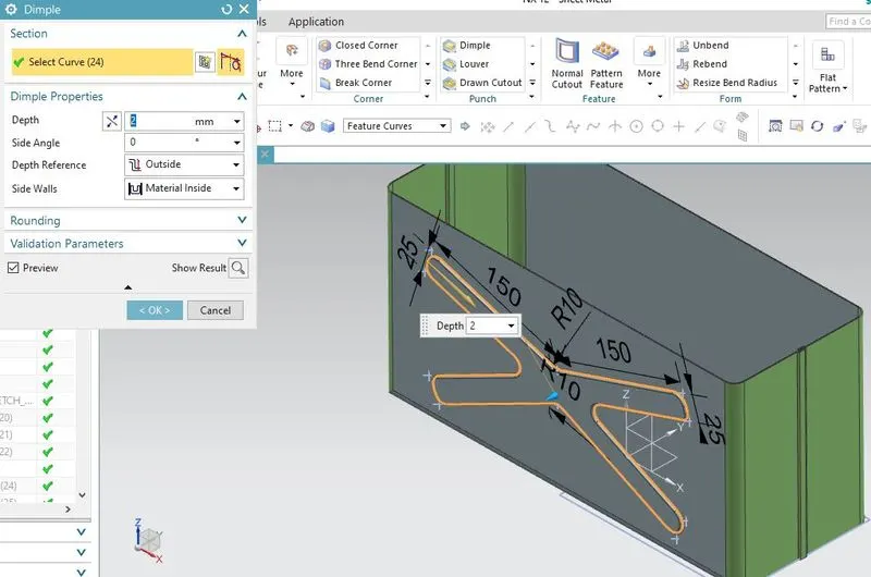
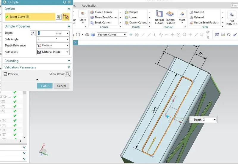
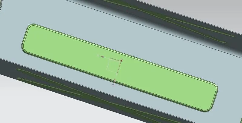
then circle of radius 5cm is drawn on the XY plane .click on bead select the circle given depth and radius as 2mm .then mirror on other 3 sides with respective to the plans.
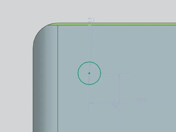
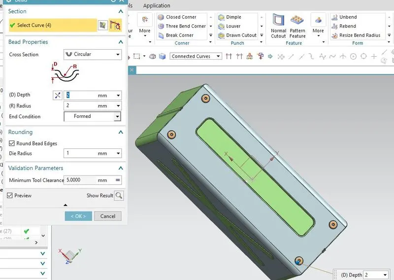
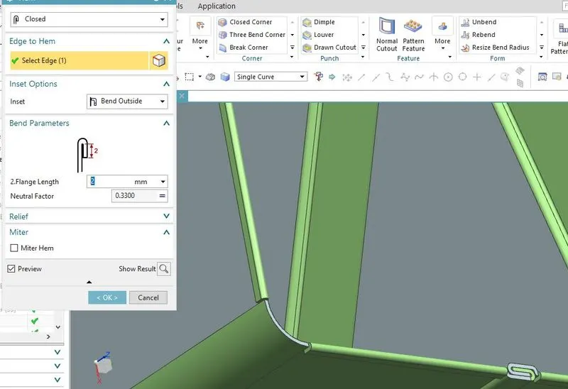
create hem flange on sides with 0.5 bend radius closed type.flsnge length 2mm.
now the box modeling is completed.
create a datum plan at 203 mm .now draw a sketch on this plan with reference to the outine of box model.given tab with base type so that lid is a separate body
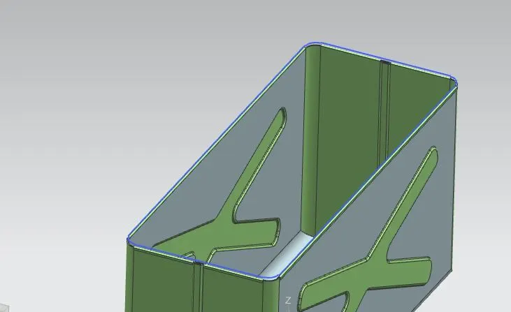
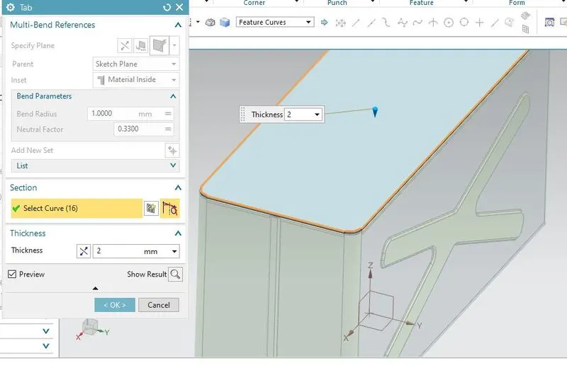
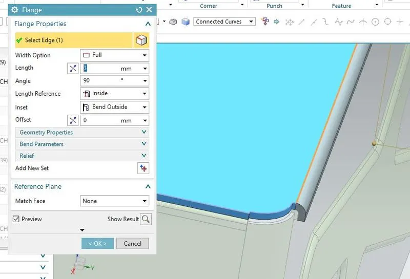
give hem flange with 1mm bend radius on all sides of the lid.
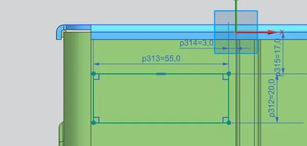
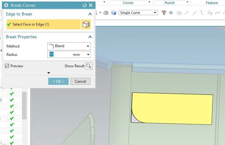
oon the vertical face of box a rectangular sketch is drawn.Click on tab command and give 1 mm thickness then given break corner at bottom left side for 10 mm radius
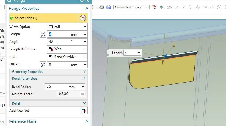
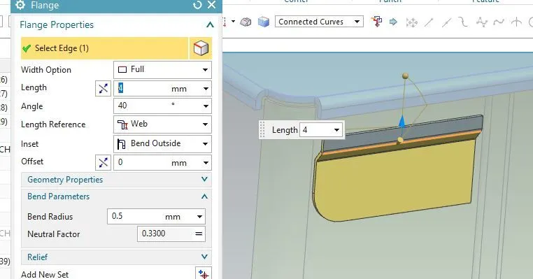
click on flange give 4mm length ar 40 degree .then again select the edge anf give flange with same parameters.
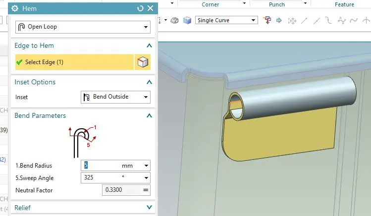
now select the hem flange command ,type as closed loop with bend radius as 5 and sweep as 325 degree.
now unbend and draw a sketch for normal cut out then rebend.
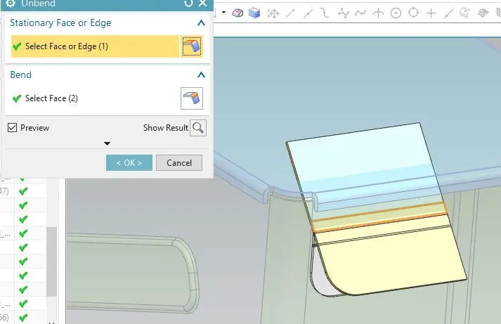
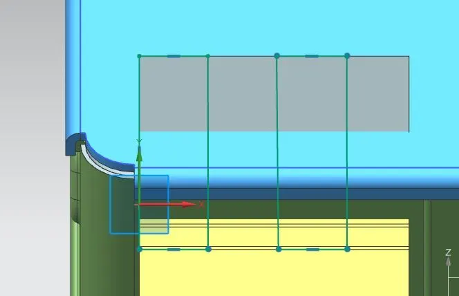
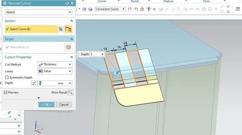
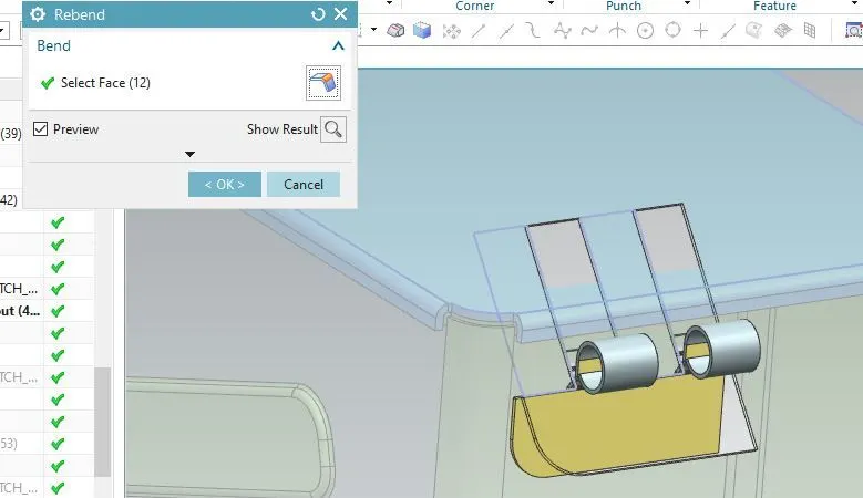
now mirror the body on the other side .
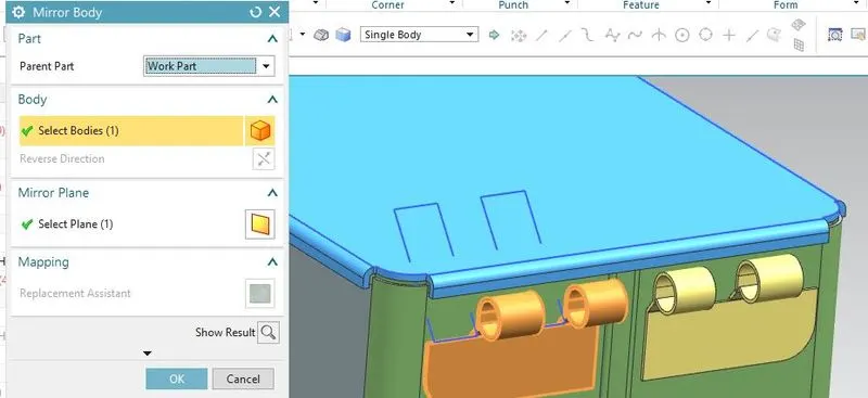
now select the upper face of the lid and drw a rectangular sketch .tab to 1mm thickness given bend corners.
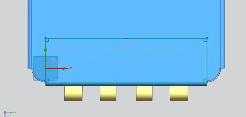
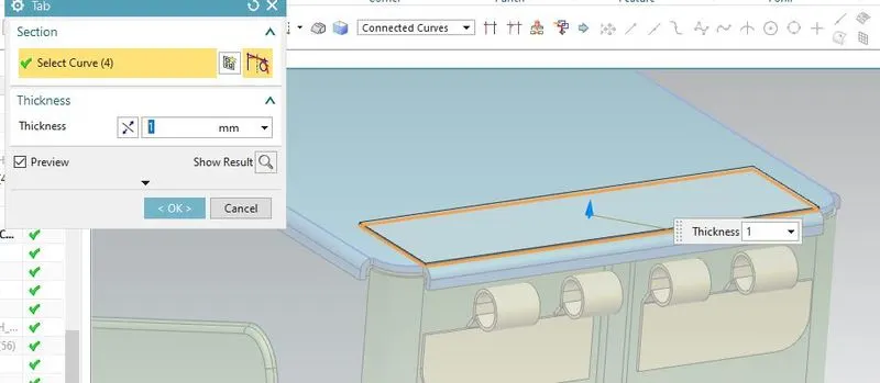
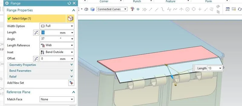
flange of 13 mm at 37 degree is given.
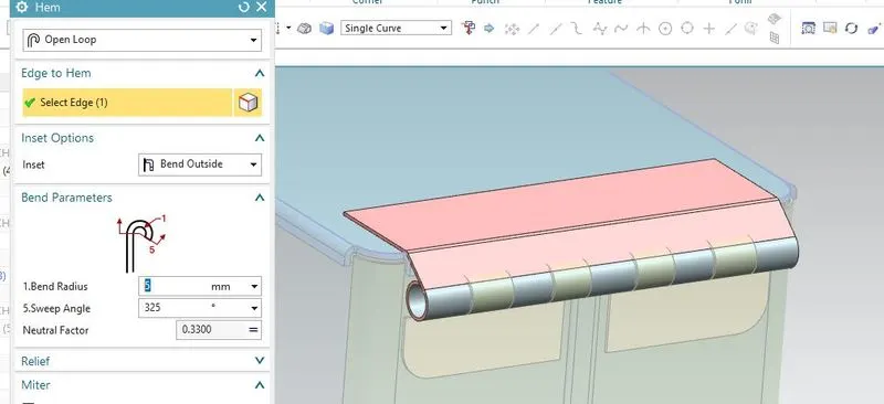
go to hem flange select the edge a,type-closed loop,bend radius as 5mm and sweep 325 deg.
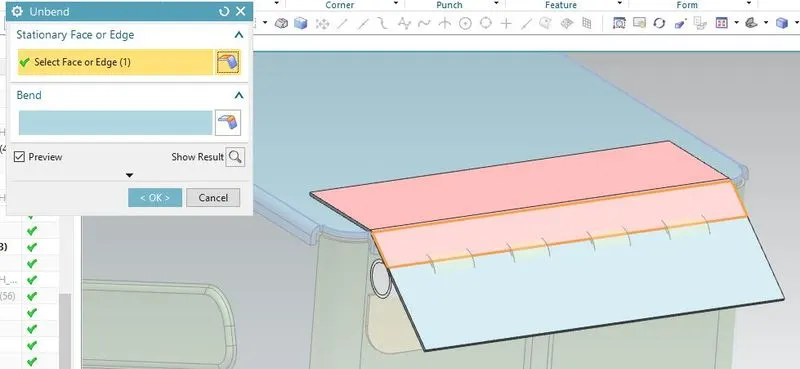
now for the normal cut out unbend the body draw the sketch and rebend.
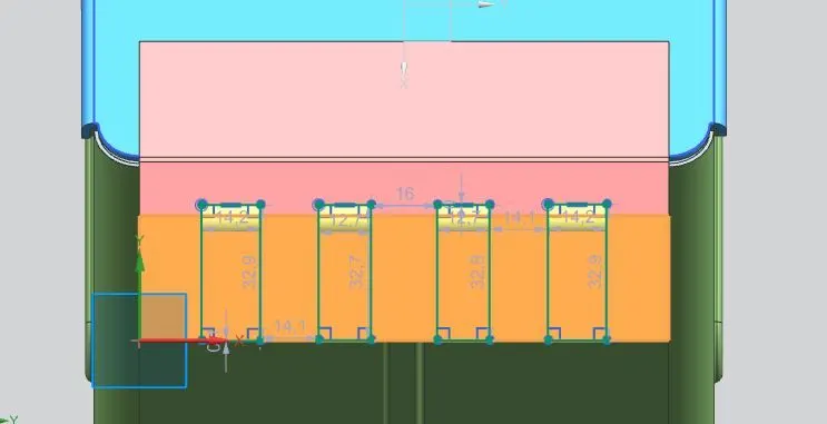
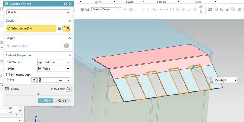
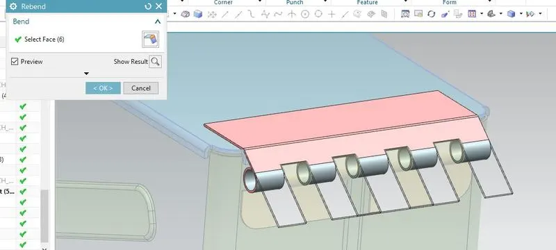
All the solid bosies have been created now flat pattern of each body is given
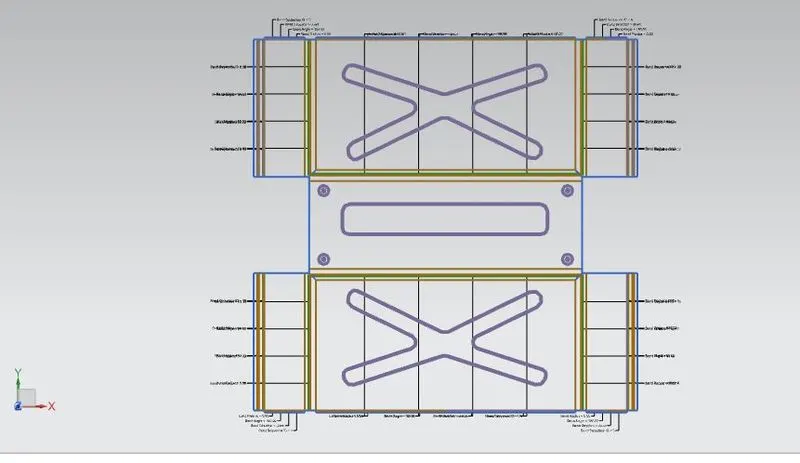
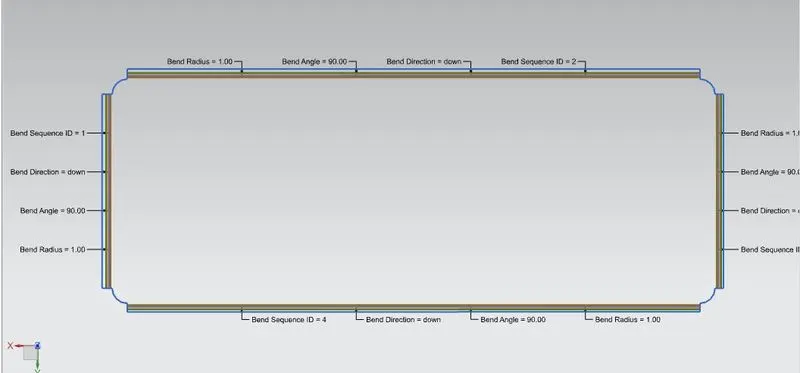
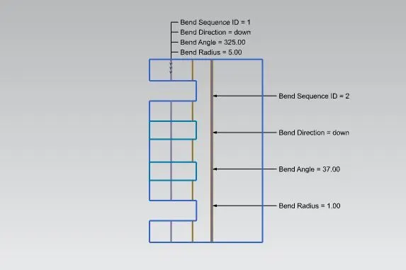
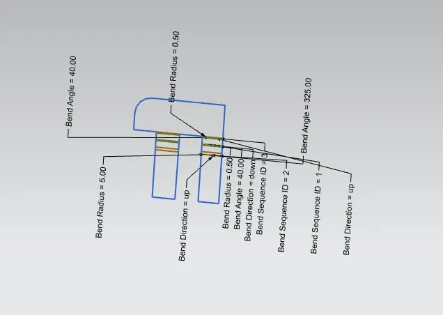
go to application and select drawing.
new sheet A2 is given.select the base view and view type flat pattern to get the drawing.
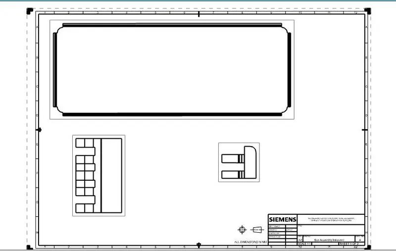
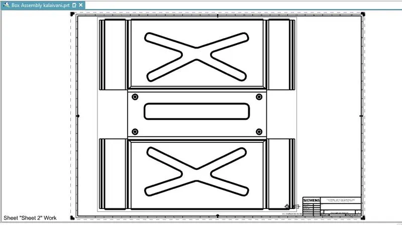
the final box assembly model is done.The part can be viewed in different mode