Advanced Sheet Metal Design Using NX Cad Challenge_1_Casing Design
CASING DESIGN USING NX CAD
OBJECTIVE
To design a sheet metal casing using NX Cad with suitable commands and create Drawing Sheet of final model.
INTRODUCTION
Sheet metal is metal formed into thin, flat pieces, usually by an industrial process. Sheet metal is one of the fundamental forms used in metalworking, and it can be cut and bent into a variety of shapes.
Thicknesses can vary significantly; extremely thin sheets are considered foil or leaf, and pieces thicker than 6 mm (0.25 in) are considered plate, such as plate steel, a class of structural steel.
Sheet metal is available in flat pieces or coiled strips. The coils are formed by running a continuous sheet of metal through a roll slitter.
In most of the world, sheet metal thickness is consistently specified in millimeters. In the U.S., the thickness of sheet metal is commonly specified by a traditional, non-linear measure known as its gauge. The larger the gauge number, the thinner the metal. Commonly used steel sheet metal ranges from 30 gauge to about 7 gauge. Gauge differs between ferrous (iron-based) metals and nonferrous metals such as aluminum or copper. Copper thickness, for example, is measured in ounces, representing the weight of copper contained in an area of one square foot. Parts manufactured from sheet metal must maintain a uniform thickness for ideal results.
There are many different metals that can be made into sheet metal, such as aluminium, brass, copper, steel, tin, nickel and titanium. For decorative uses, some important sheet metals include silver, gold, and platinum (platinum sheet metal is also utilized as a catalyst).
Sheet metal is used in automobile and truck (lorry) bodies, major appliances, airplane fuselages and wings, tinplate for tin cans, roofing for buildings (architecture), and many other applications. Sheet metal of iron and other materials with high magnetic permeability, also known as laminated steel cores, has applications in transformers and electric machines. Historically, an important use of sheet metal was in plate armor worn by cavalry, and sheet metal continues to have many decorative uses, including in horse tack. Sheet metal workers are also known as "tin bashers" (or "tin knockers"), a name derived from the hammering of panel seams when installing tin roofs.
DESIGN METHODOLOGY
DESCRIPTION
SHEET METALPREFERENCES
SKETCH
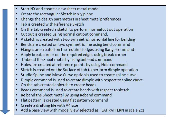
The sketch is the fundamental base element for any feature in the design of any sheet metal component. Most of the features require a sketch. The very first step is to sketch which is then used to create a tab or the base feature. So, the first sketch can be called a base sketch. For other features which are the children features of the tab, the sketch may require again on a particular plane or a face.
TAB
Tab is a command used to create a base for any sheet metal part that can be extruded from a sketch.
- Activate the “Tab” command
- Select the sketch when “Select Curve” in the “Section” tab highlighted.
- Also, you can create a new sketch by clicking “Sketch Section” in the “Select Curve” tab
- Define thickness in the thickness tab. But it is lock by the default.
tab is created after a sketch is created in any of the planes or datum plane created. The tab is always the parent feature for other features following it. In this casing design, the tab is created after a simple sketch in the XY plane.
NORMAL CUT OUT
Normal Cutout command extract volumes from sheet metal by using sheet metal production principles. Cutting faces will be perpendicular to the sheet metal surface.
- Activate the “Normal Cutout” command.
- “Select Curve” in the “Section” tab will be highlighted automatically. Select a curve to extract.
BEND
Bends sheet metal model by the reference of a line that lies on the sheet metal. Bend feature is added wherever a bend in the sheet metal component is required. It may be at any position or at any angle. A sketch is required to create a bend. It can be an open profile and it can be either a straight line or a curve
- Activate the “Bend” command.
- Select a line or create a sketch to draw a line.
- Arrange direction and side
- Double click arrows on the screen to change direction or side
- Define bend angle
- Type angle value in “Angle” box in “Bend Properties”
- To change the bending position due to line change “Inset” settings in the “Bend Properties” tab.
FLANGE
Adds flange on an edge and create a bend between two walls. The flange can only be made on a straight edge.
- Activate “Flange” command
- Select edge when “Select Edge” highlighted in the “Base Edge” Tab. (It will be automatically activated after flange command activated.)
- Select the edge to create a flange
- If you want to change the sketch section, click on “Edit Sketch” Box in “Section” tab
- Define flange properties in the “Flange Properties tab. “Angle” and “Inset” is important in this tab
BREAK CORNER
Break corner and chamfer tools are used to make some changes over sheet metal body. Rounds or chamfers a sharp corner of a tab or flange. Bend:completely formed with radius and creates smooth edges.
UNBEND
It’s an command used to flatten the created 3d model taking one face as a stationary face.This feature is used to unbend the adjacent bends and flatten them. Here it is used to create more features. This command is used to unbend the sheet metal parts to create geometries and work on complicated designs. In this command, we have to select a stationary face and then select the corners of flanges to unbend.
HOLE
It’s an command used to create different type of hole like tapping and normal drilling, on the Surface of an Sheet metal.It adds a hole to one or more solid bodies in a part or an asembly with options for counterbored, countersunk and threaded. Here six simple holes are created on the unbent surface with a diameter of 10mm. It can be used to make customized or standardized holes along with a defined point or path. The dept of the hole can be controlled
DIMPLE
It is a projection command of a particular shape with reference to sketch with certain depth.Dimples in sheet metal components provide more strength and rigidity to the flat structure of the component. Dimple feature in Siemens NX is created using the sketch created in any face or any flange of the sheet metal component.
BEAD
It is also type of projection to deform the shape at a certain point with reference to sketch and also giving strength to the material.
Beads are the features added in sheet metal components in order to increase the stiffness of the component. Beads require a sketch in order to apply the feature. It can be either an open or closed profile. For this casing design project, four small beads are applied in the symmetric position
REBEND
This command used to re bend the already flattened sheet metal.Rebends, unbended feature of the sheet metal model. It uses after the “Unbend” command If needed.
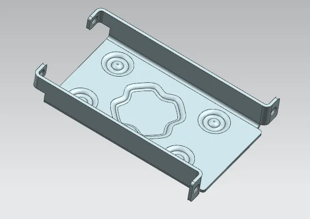
All the features added after the unbend feature are added in the unbend state itself. After the addition of sketches and additional features are completed, the sheet metal component has to be rebent to the required position. This is done using the rebend feature and selecting all the bends in order or by box selection. This completes the design process of the casing adding the features.
FLAT PATTERN
It creates a flat pattern feature from the formed sheet metal part. The user chooses this command to create a flat view of the sheet metal after unbending all the sides and faces. This view can be used in drawing the flat pattern along with the bend radius and other dimensions.The flat pattern ensures the ability to cut the sheet metal out of the raw sheet metal plate. It removes the possible errors such as interference or collision within the same component.
DRAFTING
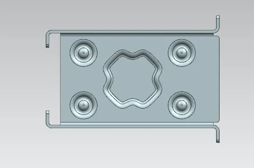
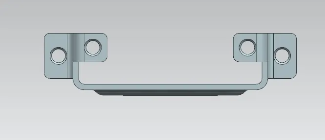
the manufacturing of the component requires a technical drawing of the component with the provided scale and with accuracy. The necessary details such as annotations, callouts, bend tables can be added as per the requirement. For this casing design project, a drawing is created with flat pattern view in 2:1 scale(A4)
VIEWS
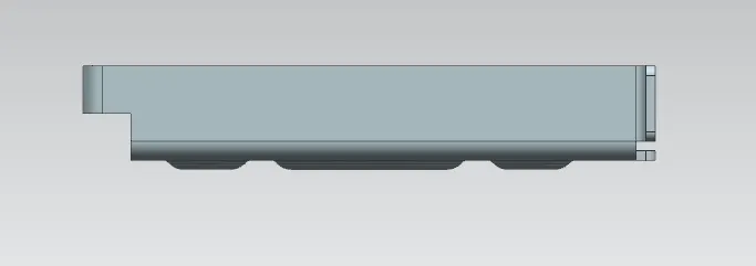
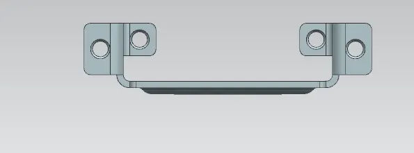
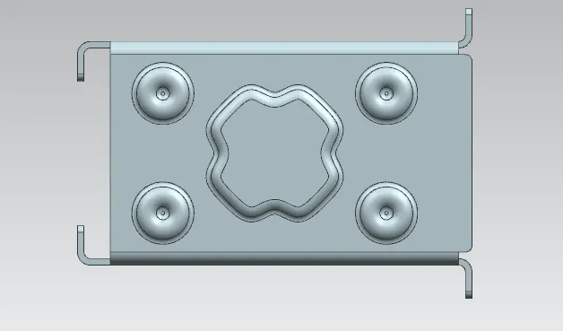
DRAWING SHEET
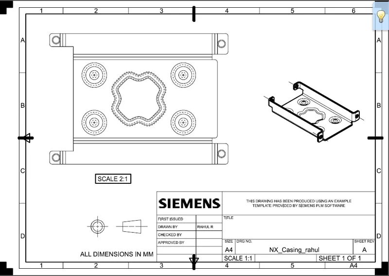
CONCLUSION
Designed a sheet metal casing using NX Cad with suitable commands and created Drawing Sheet of final model.