Advanced Sheet Metal Design Using NX Cad Challenge_1_Casing Design
Title of the Project ;-
Advanced Sheet Metal Design Using NX Cad Challenge_1_Casing Design.
Objective ;-
To design casing type of a model to use and help of NX advance sheet metal method and software.
Introduction ;-
In this project the name of NX sheet metal provide a set of tools within the NX and design environment that metal parts then dependent ont their material and manufacturing process. The NX sheet metal design and process information in sheet metal - specific modelling feature to use them, for bend, flange, tab, cutout, bead, dimple. and flat patter, base view, drafting.
We can also quickly convert the model for solid to sheet metal componenta and create sheet metal part and enclose other component. NX sheet metal specific feature such flange, tab, cutout and many more feature are used and automatic bend reliefs.
So, in this project going to desig a casing type of model and using sheet metal tools and commands for the given project.
Design Methodology :-
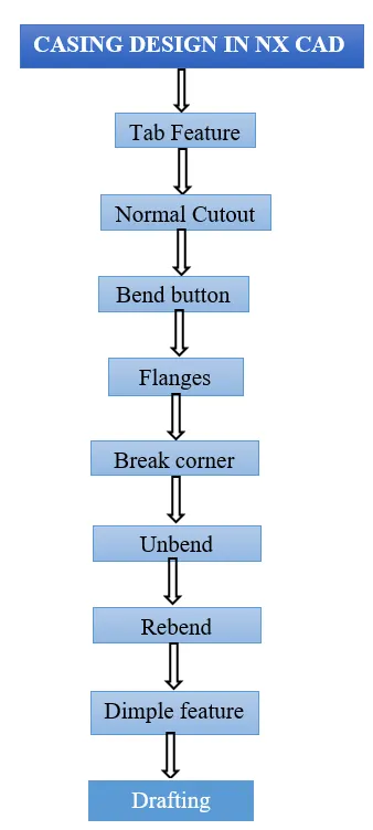
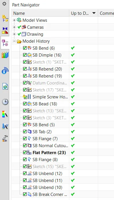
- New Sketch in XY plane and given dimension for 60 mm and 50 mm rectangle
- Changing sheet metal design parameter
- Adding thickness of 1mm by using TAB option
- Remove 5 mm x 40 mm materal use normal cutout
- Applying bend with reference line
- Applying flange of 5 mm
- Applying break corner of 1mm
- Unbending the metal sheet
- Adding holes of M2 size
- Adding dimple in sketch
- Addihng bead
- Re-bending the metal sheet
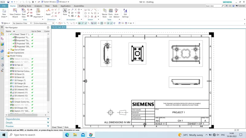
- Drafting
Description :-
Important tools which based and used during designing of casing are follow ;
- TAB
Extrude sketch and thickness value are add to material of the plane face.
- Cutout
It cuts the model perpendicular to the sketch.
- Bend
The model bending material on one side sketch line add between two sides.
- Flange
Add flange to angke and planar face add bend between the two.
- Break Corner
Rounds a sharp corner
- Unbend
Flatten a bend
- Studio spline
Create spline through define points, we can change position points or drag points while the command has been activate.
- Move curve
We can move our sketch entities to selected reference and points which makes moving sketch objects very effective.
- Dimple
Lift area of the model inside sketch that simulated stamping a tool.
- Bead
Lift material along a counter of sketch that similate stamping tool.
- Mirror Feature
It is used to mirror plane or reference.
- Rebend
Restore a bend
- Flat pattern
It create flat pattern feature from formed sheet metal part.
- Base view
It is used to create model view on the sheet.
CONCLUSION :-
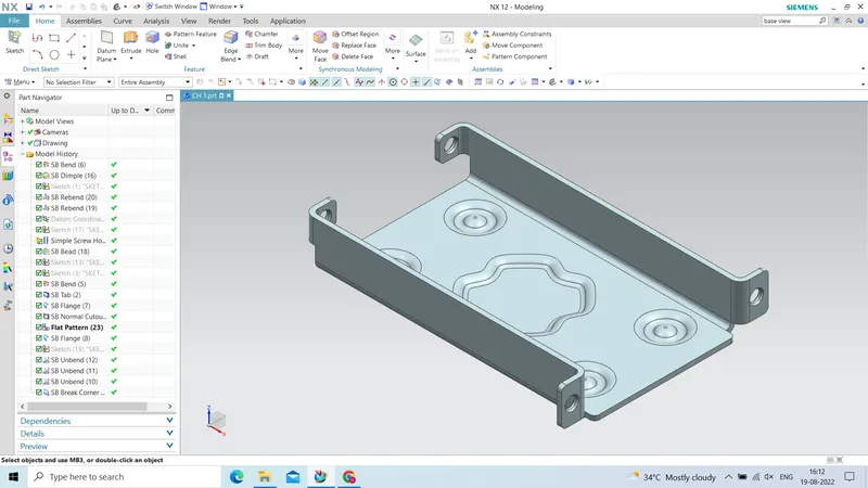
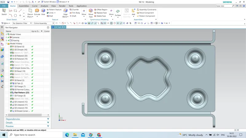
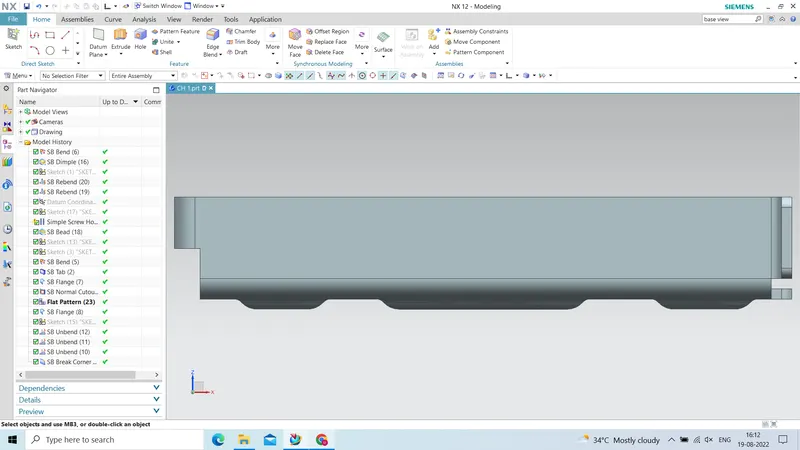
The given NX casing model explain detailed and views are explain detailed and show them .