Advanced Sheet Metal Design Using NX Cad Challenge_1_Casing Design
MODELLING OF CASING
OBJECTIVE: This project aims to design the casing using sheet metal modelling in the NX cad sheet metal workbench.
INTRODUCTION: The present project to develop a casing using NX Cad requires convenient designing along with subsequent operations to perform to get the desired casing design. The following operations are performed on the casing are as follows:
- Tab
- Normal cutout
- Bend
- Flange
- Break corner
- Unbending
- Holes
- Dimple
- Beads
- Rebending
All the sketch profiles are made fully constrained with respect while performing the subsequent operation with the following sketches. The flat pattern obtained at the end is used for drafting using an A4 sheet and the base view as a flat pattern.
DESIGN METHODOLOGY: The flow chart resembles the sequence in which the process follows:
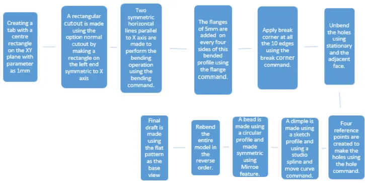
DESCRIPTION: The casing is designed with subsequent operations that use various features described as follows along with the flow with which we design the casing. After sketching the XY plane it is extruded using the tab command with global parameters of 1mm.
Tab- This feature is used to extrude a thin surface of applied thickness by extruding along a certain direction and the sketch is usually a closed path.
After this, a sketch section is made on one side symmetric to the X-axis to get a cut-out using a normal cutout feature.
Normal Cut-out- This feature takes out the sheet metal section from the extruded part and is used to extract a surface from the previously created tab.
A line-symmetric to X-axis is made on both the sides along which the bend command is used.
Bend- If we need to bend out sheet metal parts in a certain direction one can use this command along with the sketch reference along whom it is bent. The two-line references previously made are used as a reference along which the sheet metal part is bent to get the desired result.
The four corner sections are provided with a flange using the range command.
Flange- When one needs to add a flange along a reference edge using the reference face, this command is used. All the four corner edges are added with flanges to get the desired result.
All the sharp edges are provided with a blend by using a break corner command.
Break Corner- It is similar to a fillet feature where a blend is used to provide a smoother section with a suitable radius.
The following part obtained until now is unbent using the unbed feature in sequential order.
Unbend- To unbent back the bent sheet a stationary face along with the stationary edge is used and the adjacent face is then unbent. This operation is applied in proper order until the desired result is obtained.
On this unbent sheet, four sketch reference points are made to provide a hole by using the sketch feature and the hole command.
Hole- A clearance hole is added on all the four reference points made previously by using the suitable hole of M2 screw size and the H13 fit.
After the a sketch reference is created to make a dimple on the XY plane. This sketch made is then improved by using the studio spline and the move curve option to get the desired result. The studio spline option bent the reference points along with the sketch by using poles.
Dimple- This feature is used to emboss a certain profile over the sheet metal by using the sketch reference up to a certain depth similar to punch. The sketch made is punched to a depth of 1mm along with rounded corners.
After the dimple is created a sketch reference of the circle is made which is then mirrored by using the mirror command. It is used to make the beads on the sheet metal part.
Beads- The beads are also similar to the punching operation which embossed the sketch on the sheet metal part. The circle made is punched up to a certain depth and this bead made is mirrored and the then two beads are made symmetric along the X-axis.
After the desired result is obtained the sheet is rebend using the rebend command. This is done in the exact reverse order with which it was unbent.
Rebend- Similar to selecting the reference edge and the stationary face this command is used to get back the result.
Finally, a draft is made by using the flat pattern as a base view using an A4 sheet with a 2:1 ratio. The flat pattern tool is used to obtain the base view beforehand.
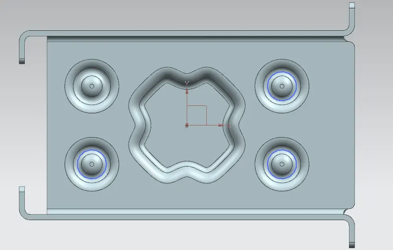

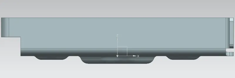
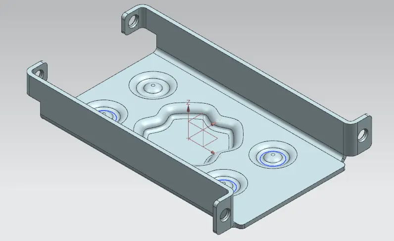
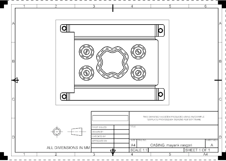
CONCLUSION: Hence the design of the casing along with the draft is done successfully.