Advanced Sheet Metal Design Using NX Cad Challenge_1_Casing Design
DESIGN and MODELLING of SHEETMETAL CASING in NX-12
Objective:-
# To design and model the sheet metal casing in NX-12 by using some basic features.
# To learn to create sketches on defined planes as per requirement.
# To master the user interface and basic features of Sheetmetal application in NX-12 like Tab, Flange, Break corner, Unbend, Creating holes, Rebend, Dimple, Bead, Mirror feature, and Flat pattern.
Forming Basics:-
Bending :- Bending is a process whereby a force is applied to sheet metal which causes it to bend at an angle and form the desired shape. Bends can be short or long depending on design requirements.
Critical Dimensions :-
The following are some terminologies that are used in sheet metal. Designers need to adhere to machinery guidelines when designing for bending. Bends can be characterized by these parameters. Some critical dimensions that need to be considered when setting up sheet metal in CAD software are sheet metal thickness, the k-factor, and bend radius. One needs to check that these factors are consistent with the tooling that will be used in manufacturing. This guide gives important guidelines for good design practice.
Design Methodology / Approach:-
Tab – Tab is the basing feature in the sheet metal environment of NX-12. The tab is the initial or the start-up stage of the design of the sheet metal component. By using the Tab feature, we create a base for sheet metal component and decide the thickness of the sheet metal which is then followed in the further steps of design.
Bend – Bend feature is used to part of the flat tab into the flange. It uses a sketch that includes bend lines. Bend can be created either side of the bend line.
Flange – Flange feature is used to create an extended portion or bend to the selected edge. While creating flange we have to set different parameters such as length of the flange, its angle, length reference ( inside, outside, or web), inset ( Material inside, Material outside or bent outside). Other parameters like bend radius, bend relief, and Neutral factor is also needed to be considered.
Break Corner – This feature is used to smoothen the harmful corner of the Sheet or to give an attractive look to the part.
Unbend – This feature is used to flatten the sheet metal part for further design operations.
Hole – This feature adds holes to the sheet metal part.
Dimple – This command is Use to lift an area of the model inside a sketch that simulates a stamping tool. We can create an indentation in a sheet metal part using a sketched section as the dimple outline. The Dimple command makes an indentation in the sheet metal part, using a sketched section as its outline.
Bead – The bead is like a raised rib in the sheet metal panel. It requires that you have at least one sheet metal panel in the active part as well as an open or closed-loop sketch.The Bead is another feature that has only a button for Options on the Command Bar.
Flat Pattern – This feature is used to create an instance of the flat shape and size of the sheet metal that required to create the final part
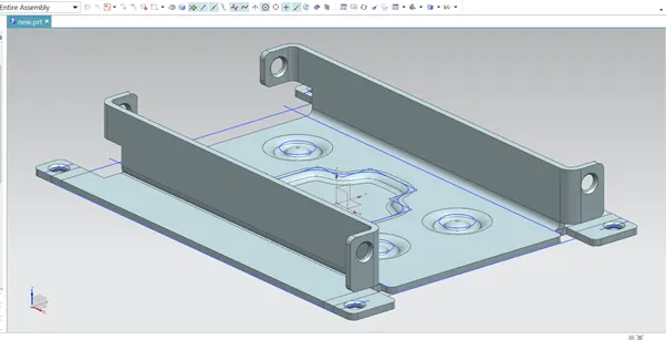
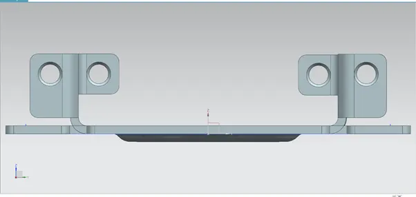
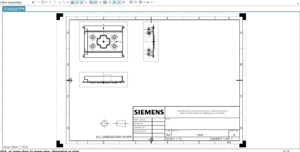
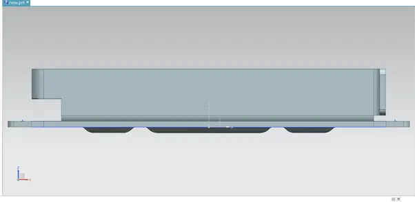
Images of Sheetmetal casing Designed in NX-12 Sheetmetal Enwironment:-