Advanced Sheet Metal Design Using NX Cad Challenge_1_Casing Design
CHALLENGE 1 CASING DESIGN
TITLE: Casing design
OBJECTIVE: To model casing design in sheet metal using NX CAD
OUT PUT REQUIRED:
Title of the Project
Objective
Introduction
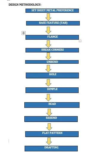
Design methodology / approach (To be explained with the help of Flowcharts only)
Description (Need to explain tools/ Features used while designing)
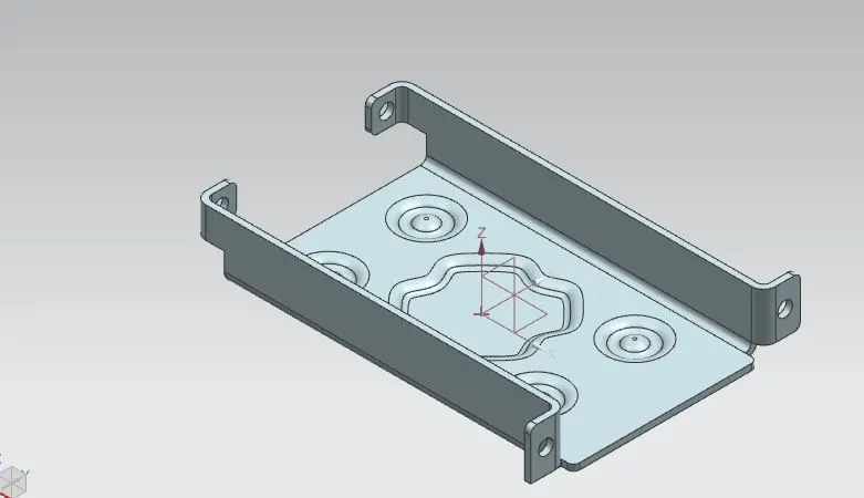
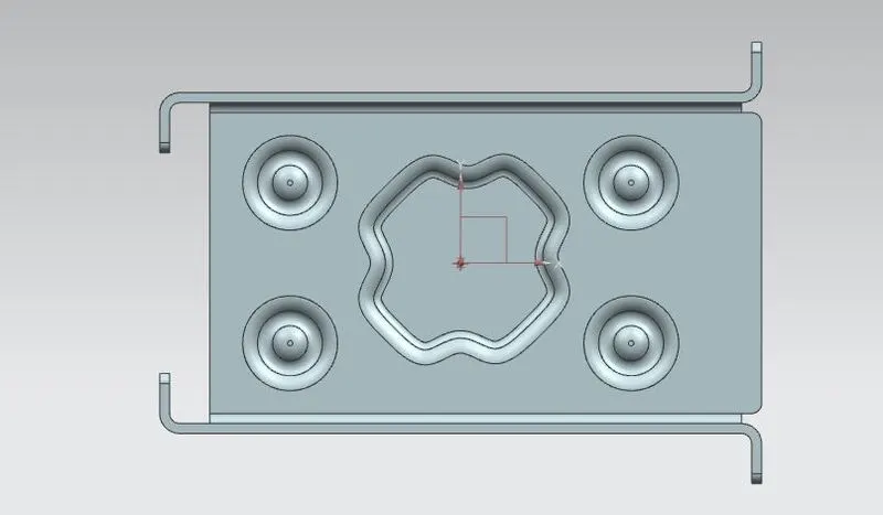
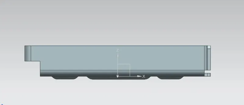
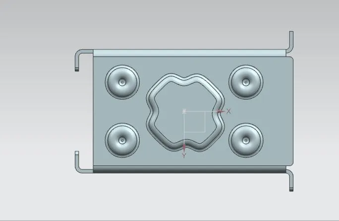
Upload a min of four screenshots of Model in the report. (Front View, Side View, Isometric View and the Top View)
Attach Detailed Drawing Sheet Image
Conclusion
INTRODUCTION: Casing is an enclosure design to keep the parts protected. Now using
NX CAD sheet metal casing is designed.
DESCRIPTION:
As per the recommended work flow the base feature is created.
New – sheet metal part-menu-preferences-sheet metal preference.
The global values are set to 1mm.
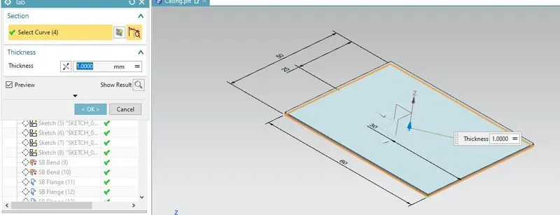
The sketch is drawn with rectangle of 50x60mm in XY plane. Then TAB is used to create a solid body.
The directions can be given accordingly
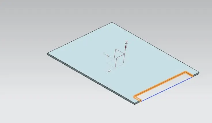
Then a rectangle OF 5X40mm at the left corner is sketched for a cut out. Finish the sketch.
Click on NORMAL CUTOUT and select the sketch the cut out is made
Now we are going to bend the side’s .click on sketch in the same plan draw a horizontal line at 10mm from the top similarly on the other side. Exit the sketch.
Under more- go to- BEND and select the line bend is formed. Same is done on the other side
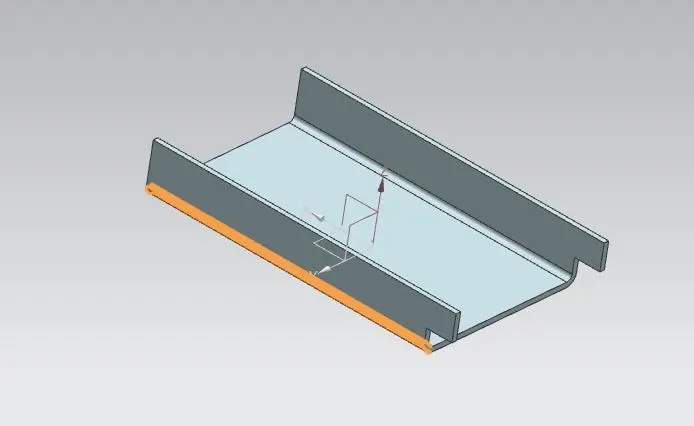
after that FLANGES are added. Click on the flange command and select the sheet metal edges. On the normal cut side the flange is given inside direction and on other side outside.
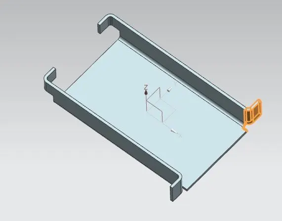
BREAK CORNERS –click on the break corner command select the edges under blend method it is created
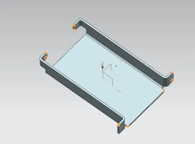
Now click on UNBEND select the stationary face and adjacent bend to form unbend.
To add features like hole dimple the part is unbend.
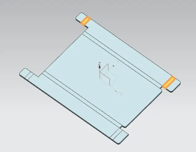
Draw a line in the left lower part with reference to xy plane create a point at the center of the line. Using mirror feature the point is created on the other side. Similarly a point is made on all corners. Exit sketch.
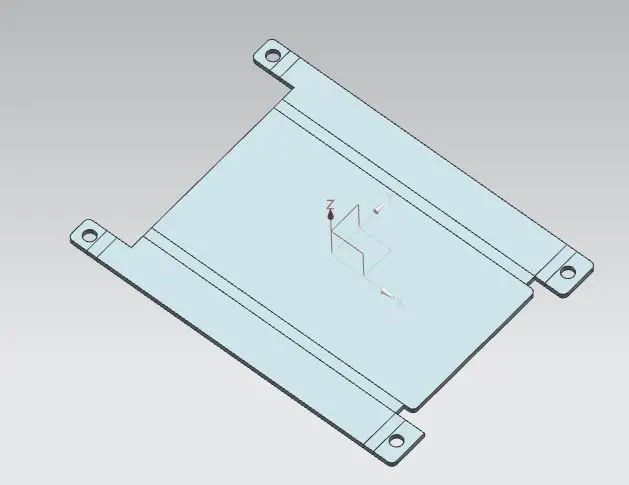
Take the hole command select the point, type –screw clearance hole, give form –simple.
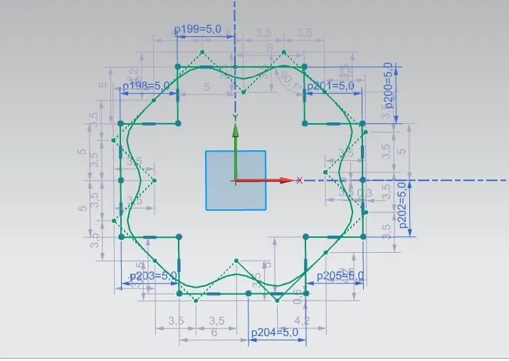
For dimple create a sketch of 5mm height and width as shown. Then click on studio spline and select the points in the line to get the curve. Studio plain -type-by poles-angle 3 degree. Then use move curve-select the spline – angle with 45 degree to get the final sketch
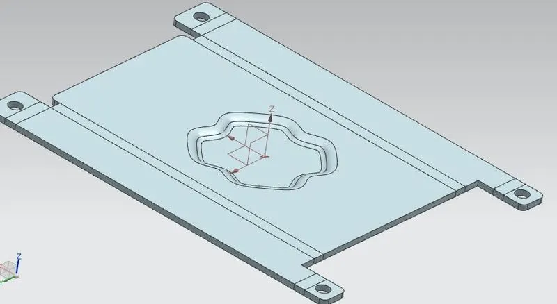
Click on DIMPLE select the curve give depth of 1 mm .All the parameters like rounding, punch radius, die radius are given as 1mm .The dimple is created accordingly by setting the depth reference and side walls
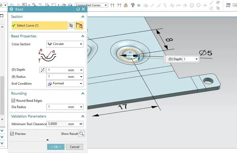
BEADS. Draw a circle of 5mm and use command bead to add bead give directions.
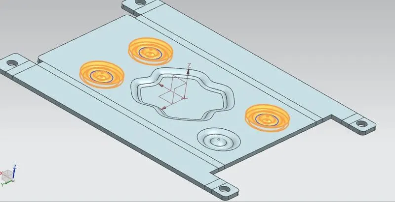
Using mirror feature and create beads on other sides with reference to the planes
Now click on the REBEND command and select the full body.
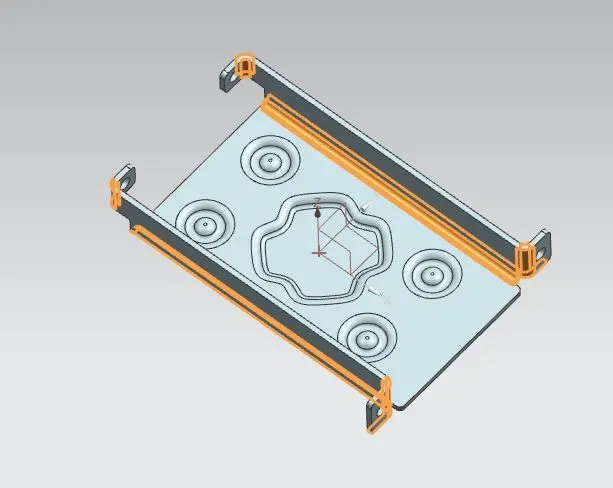
Finally to get the FLAT PATTERN click on flat pattern to view this go to model views in part navigator and double click on flat pattern.
DRAFTING new sheet-select base view change the view to flat pattern and select the location. Drawing of flat pattern
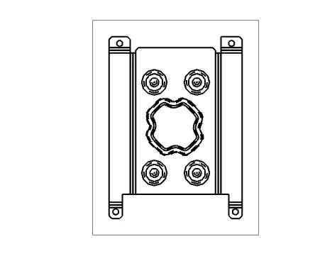
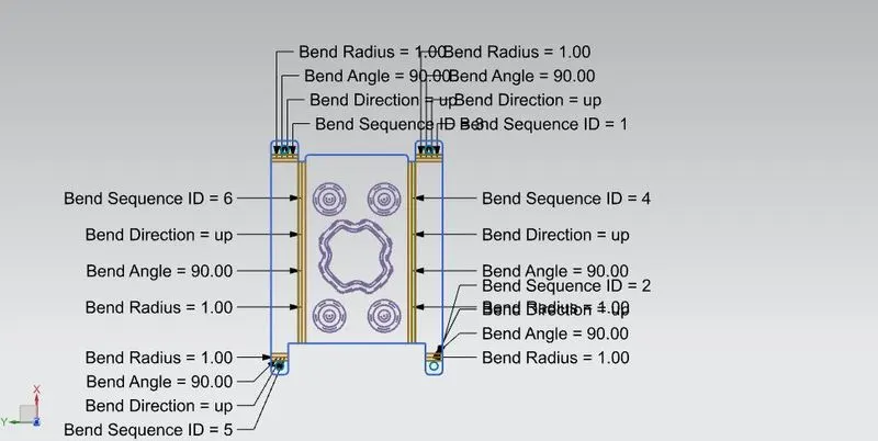
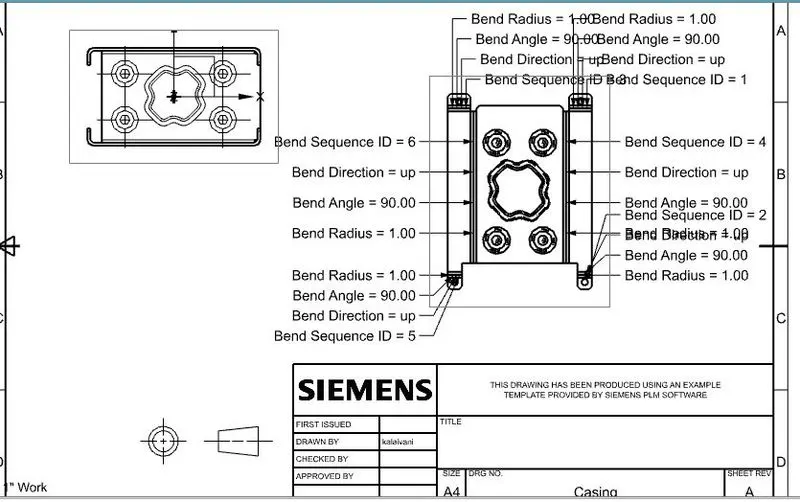
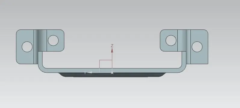
Both the files should be saved.
CONCLUSION: Casing design is done in sheet metal using NX CAD