Advanced Sheet Metal Design Using NX Cad Challenge_1_Casing Design
CASING DESIGN
OBJECTIVE:-
To design a ‘Sheet metal Casing’ using Siemens NX Sheet metal Application.
INTRODUCTION:-
In this challenge, by using NX sheet metal application design the Sheet Metal Casing by using various tools like tab, normal cut out, bend, break corner, dimple and bead.
DESIGN METHODOLOFY:-
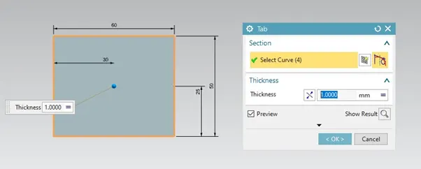
- Make a rectangular sheet metal using Tab button.
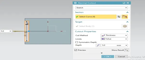
- Make Normal Cutout.
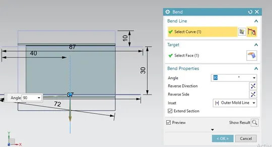
3. Make a bend
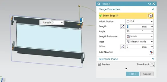
4. Make 4 Flanges.
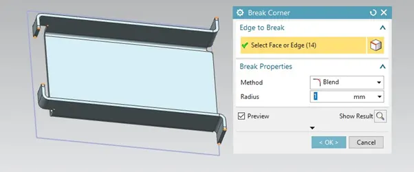
- Break corner to make smooth corners.
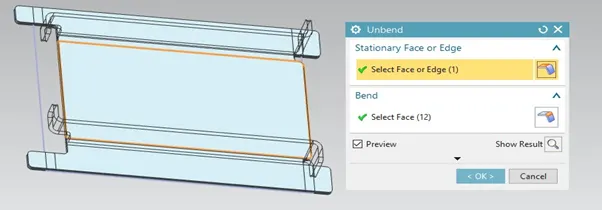
- Unbend the sheet metal.
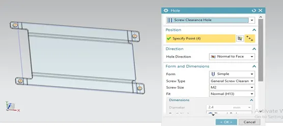
- Make a screw hole in four corners.
- Using studio spline, move curve and Dimple button make a sketch on sheet.
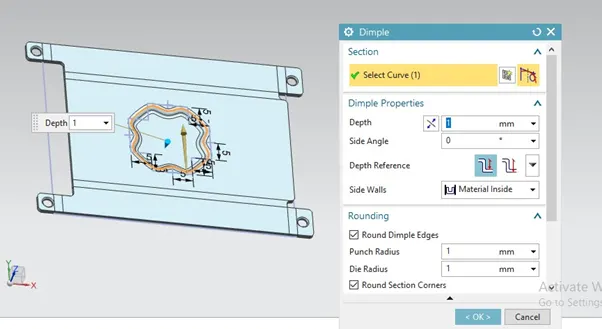
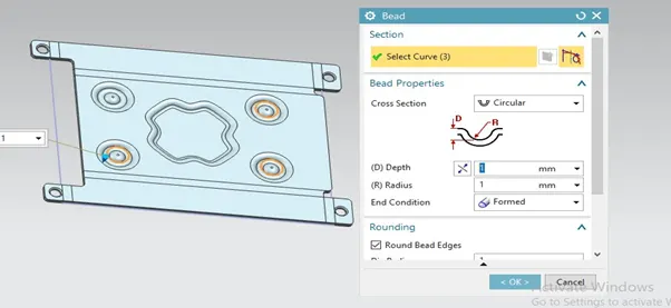
- Make 4 Beads on sheet metal.
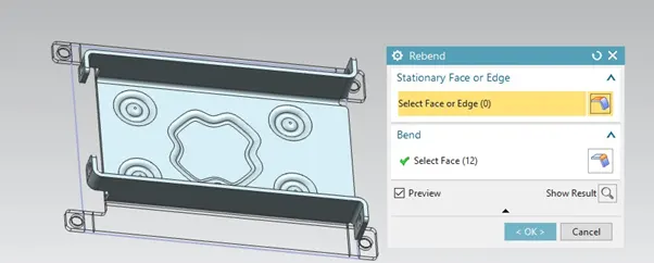
- Re bend the sheet metal.
- Make Flat pattern view on sheet metal.
Description:-
- Tab: - Use this command to create a base feature by extruding a sketch along a vector by thickness value, or by adding material to existing faces & bend regions of a sheet metal part.
- Normal Cut out:- Use the Normal Cut out command to cut material by projecting a sketch onto the model and then cutting perpendicular to faces intersected by the projection. We can use planar sketches or 3D curves to specify the section for the normal cut out.
- Bend:- We generally use this command to turn a sheet metal in various angle.
- Flange:- Use this command to add a flat flange at an angle to a planar face and add a bend between the two. Bend consists of a two region
- BEND 2. WEB
- Break Corner:- Use the break corner command to round or chamfer sharp corners of a tab or flange.
- Unbend:- Usethe Unbendcommands to unbend and rebend non-uniform thickness bends.
- A Screw Hole :- This command use for create a screw size hole in sheet metal.
- A Studio Spline:- Usethe Studio Splinecommand to dynamically create splines using either points or poles.
- Move Curve:- Usethe Move Curvecommand to move or rotate a set of sketch curves.
- Bead:- Use the bead command to lift material along the contour of a sketch that simulates a stamping tool. Beads can also be created to stiffen sheet metal part.
- Rebend:- Usethe Rebendcommands to unbend and rebend non-uniform thickness bends.
- Flat pattern view :- A flat patternis a 3D sheet metal model in a flattened state. Create Flat Patterncalculates the material and layout required to flatten a 3D sheet metal model. The part browser displays a Flat Pattern node, and the flattened state of the model displays when this node is active.
Various views in CASING DESIGN:-
- Top view:-
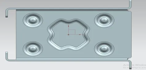
2. Isometric View
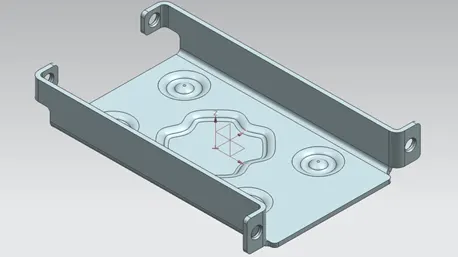
- Bottom view:-
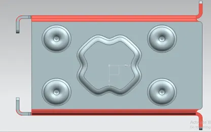
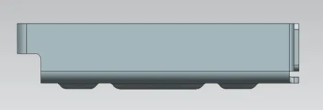
4. Front View:-
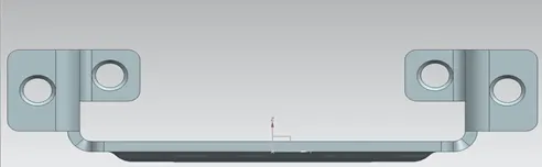
- Right Hand Sided View:-
- Flat Solid View:-
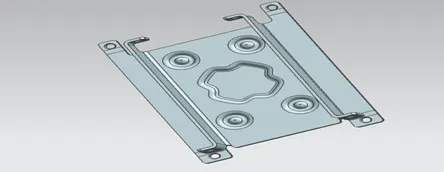
- Studio View:-
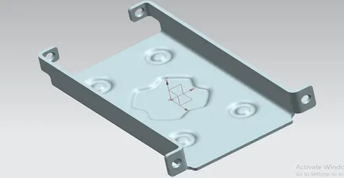
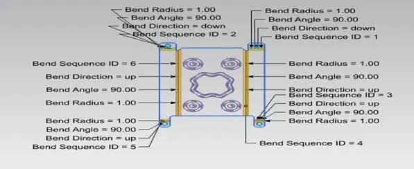
- Bend Angle View in A4 Size :-
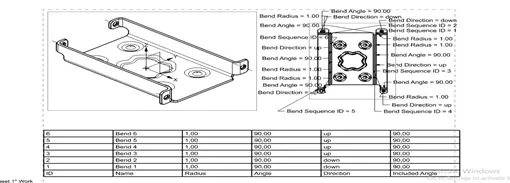
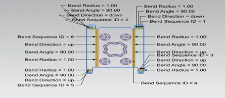
Conclusion:-
By using various commands in sheet metal design CASING DESIGN is created by various features.
Google Drive Link
https://drive.google.com/file/d/1ZS5fSxgjk9vG0xND581dCpSH6OZfs0Pm/view?usp=sharing