ADAMS - Project - Hardpoint tuning to achieve pitch gradient targets using suspension “anti” characteristics
Introduction:
Understanding Pitch in Vehicle Dynamics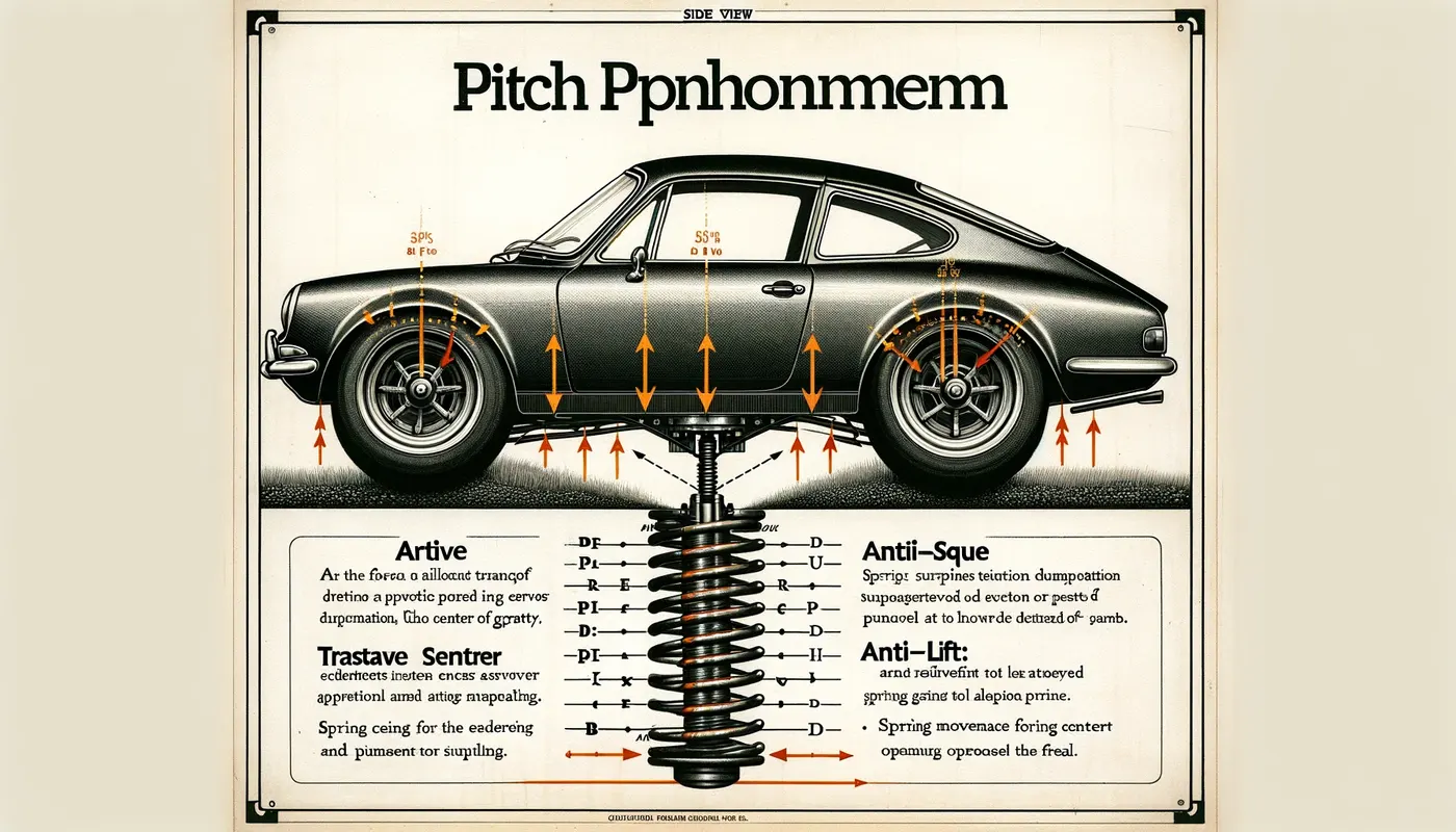
Pitch refers to the rotational movement of a vehicle's body about a transverse axis, which extends from the left to the right side of the vehicle and passes through its center of gravity. This motion is a direct response to acceleration and braking forces.
Pitch Angle: Defined as the angle made by the vehicle's body when viewed from the side, pitch is considered positive when the vehicle's nose moves upward and negative when it moves downward.
The Mechanics of Pitching:
The pitching motion results from the load transfer between the front and rear axles, causing the springs to extend or compress. This dynamic is influenced by the vehicle's 'anti characteristics,' which are aspects of the suspension geometry that manage the interaction of longitudinal and vertical forces between the sprung (body) and unsprung (wheels and axles) masses.
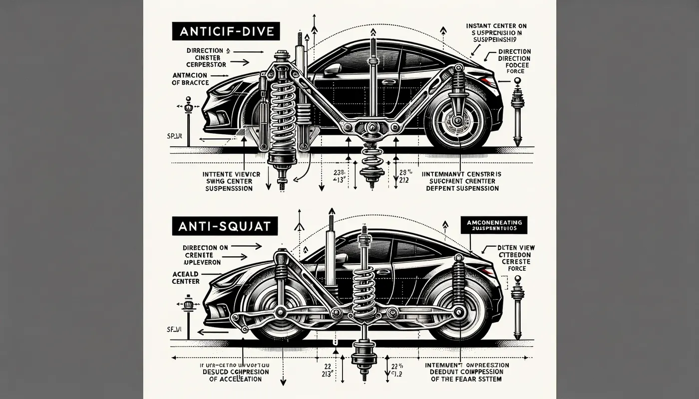
- Anti-Dive: Implemented to minimize front suspension compression during braking.
- Anti-Squat: Aims to reduce rear suspension compression during acceleration.
- Anti-Lift: Helps to lessen front suspension rebound during acceleration and the rear suspension rebound during braking.
Tuning for Optimal Performance:
These anti-characteristics are intricately linked to the side view instant center location—the point where suspension links if extended, would intersect. The instant center's position, characterized by its angle and distance from the wheel center, is finely adjusted during hardpoint tuning to enhance the desired anti-characteristics. This adjustment effectively distributes the longitudinal load transfer through the suspension links and the springs. However, the total load transfer remains constant, as it is governed by the center of gravity's height, the vehicle's weight, and its wheelbase.
The Adams sign convention is crucial for establishing a common understanding of how simulation data is interpreted. This convention specifies that:
- For the front suspension, when the instant center (IC) is positioned behind the wheel center, the swing arm is considered to have a positive length. Conversely, for the rear suspension, a positive swing arm length occurs when the IC is ahead of the wheel center.
- The angle of the swing arm relative to the horizontal is also significant. A positive angle for a positive-length swing arm means it slopes downward from the wheel center. If the swing arm has a negative length, a positive angle means it slopes upward from the wheel center.
Models Opening: The process begins with the opening of two specific suspension models within Adams software:
- A front suspension model with a Short Long Arm (SLA) design.
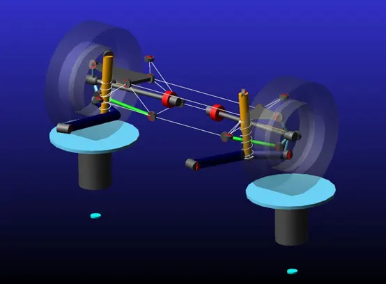
- A rear suspension model featuring a multilink setup.
Modifying Adams Springs:
-
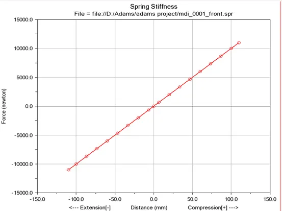
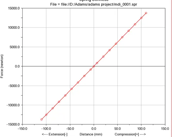
Front Suspension: The spring stiffness of the front SLA suspension was modified to a value of 100 N/mm. The modification is reflected in the changes in the spring curve, where the slope represents the stiffness. The 'before' image likely shows a different slope, indicating a different stiffness value, while the 'after' image shows a steeper slope indicative of the increased stiffness to 100 N/mm.
-
Rear Suspension: Similarly, the spring stiffness of the rear multilink suspension was altered to 125 N/mm. The graphical representation would show the initial spring curve before the change and the updated curve after the adjustment, with the 'after' image showing a steeper slope corresponding to the higher stiffness value.
Modifications of Motion Ratio:
In the process of suspension tuning, the hard points — the pivotal connections of the suspension components to the vehicle's frame — are meticulously adjusted. The objective is to refine the motion ratio, which is the ratio of wheel travel to suspension travel. Achieving the correct motion ratio is vital as it directly influences the suspension's effectiveness in cushioning the ride and maintaining tire contact with the road.
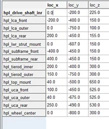
Front tuned hardpoint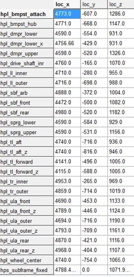
Rear tuned hardpointFor this project, the hardpoints were modified to match the specific motion ratios provided in the problem statement. This alignment is crucial to ensure that the results from analytical calculations correspond accurately with those derived from Adams simulations. Consistency between these two sets of results is essential for validating the suspension design and making informed decisions about further modifications.
By matching the motion ratios, the suspension's response to bumps and road irregularities can be optimized, affecting ride comfort, handling, and vehicle dynamics. It also ensures that the spring and damper components operate within their intended range, providing the desired level of support and damping to the vehicle's structure.
-
Front Motion Ratio Tuning:
- The hard points for the front suspension were adjusted to achieve a motion ratio of approximately 0.48. This ratio indicates how the spring and damper will compress in response to wheel travel. A lower motion ratio means the spring and damper compress less for each unit of wheel travel, resulting in a firmer ride.
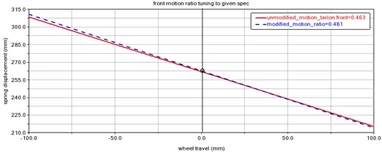
- The hard points for the front suspension were adjusted to achieve a motion ratio of approximately 0.48. This ratio indicates how the spring and damper will compress in response to wheel travel. A lower motion ratio means the spring and damper compress less for each unit of wheel travel, resulting in a firmer ride.
-
Rear Motion Ratio Tuning:
- Similarly, the rear suspension hardpoints were tuned to achieve a motion ratio of approximately 0.59. This higher motion ratio suggests that the rear suspension will have a slightly softer response compared to the front, which can be beneficial for maintaining traction and comfort during acceleration and cornering.
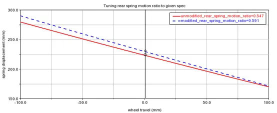
- Similarly, the rear suspension hardpoints were tuned to achieve a motion ratio of approximately 0.59. This higher motion ratio suggests that the rear suspension will have a slightly softer response compared to the front, which can be beneficial for maintaining traction and comfort during acceleration and cornering.
-
Input Parameters:
- Specific parameters for the front and rear suspensions were inputted into the simulation software. These parameters include tire model, stiffness, vehicle mass, center of gravity height, wheelbase, drive ratio, and brake ratio. Accurate input of these parameters is essential for reliable simulation results.
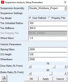
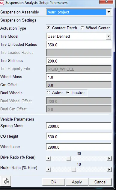
- Specific parameters for the front and rear suspensions were inputted into the simulation software. These parameters include tire model, stiffness, vehicle mass, center of gravity height, wheelbase, drive ratio, and brake ratio. Accurate input of these parameters is essential for reliable simulation results.
-
Parallel Wheel Simulation:
- A parallel wheel simulation was run, likely to ensure that the suspension behaves correctly under symmetric conditions. This step is part of validating the suspension design before moving on to more complex scenarios.
-
Tuning Hardpoints:
- The goal of hardpoint tuning is to achieve the required target values for suspension behavior. This includes adjusting the location of the hard points to achieve the desired motion ratios, as well as other performance targets such as roll center height, camber gain, and toe change.
-
Front and Rear Hardpoint Targets:
- The final step involves refining the hardpoint locations for both the front and rear suspensions. The targets for these adjustments would have been determined by the desired vehicle dynamics characteristics. The hard points are tuned to ensure that the suspension system meets these targets when the vehicle is subjected to forces during acceleration, braking, and cornering.
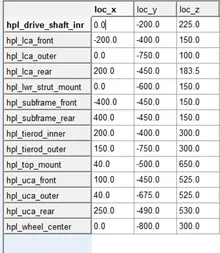
Modified Front hardpoints to achieve target results.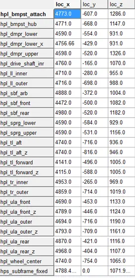
Modified Rear hardpoints to achieve target results.
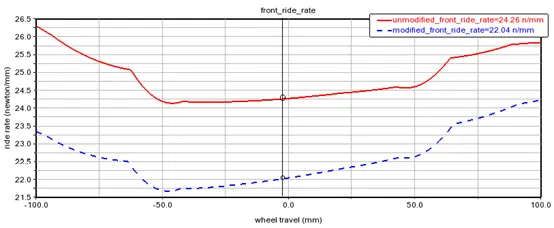
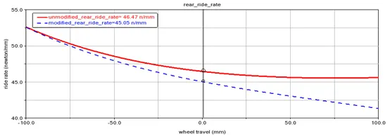
- Ride Rate: This indicates the spring rate as experienced by the vehicle occupants. A higher ride rate typically means a firmer ride.
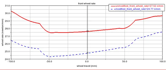
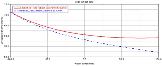
- Wheel Rate: A measure of the stiffness of the wheel as it moves up and down, which affects how the vehicle responds to road imperfections.
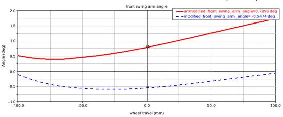
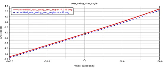
- Swing Arm Angle: The angle of the swing arm affects the camber of the wheel during suspension travel, which in turn influences tire contact with the road and handling.
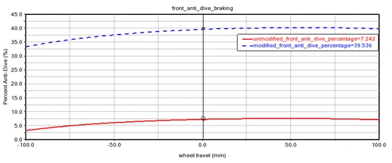
- Anti-Squat/Anti-Dive: These percentages indicate the tendency of the vehicle to squat under acceleration or dive under braking, respectively. Tuning these characteristics can improve vehicle stability during dynamic maneuvers.
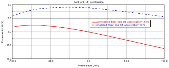
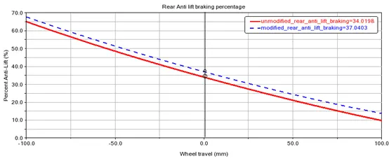
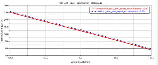
To summarize the results and present them clearly, we can compile the target achievements and deviations into a table format:
Parameter Result Target Deviation (%) Acceleration Pitch Gradient 2.2586 2.25 0.3820 Braking Pitch Gradient 1.6089 1.60 0.5573
- Ride Rate: This indicates the spring rate as experienced by the vehicle occupants. A higher ride rate typically means a firmer ride.
- The final step involves refining the hardpoint locations for both the front and rear suspensions. The targets for these adjustments would have been determined by the desired vehicle dynamics characteristics. The hard points are tuned to ensure that the suspension system meets these targets when the vehicle is subjected to forces during acceleration, braking, and cornering.
-
-
- A front suspension model with a Short Long Arm (SLA) design.
- Rajat PanchalVery good material for anti pitching characteristics
- Sandeep Gunnaputhanks_mate
- Rajat PanchalThere is one doubt in your calculation. In part where you find "front end deflection under load" you use Ød, so what does that stands for?
- Meet LadGood material bro but didn't get concept of phi d in the last third page... Of u have a new clear material of it can you upload it . It should be better to understand.
- Sandeep Gunnapupi-D are anti-dive and squat angles
- Meet LadHey bro .. sorry for pinging you again but we didn't get how we can find that phi-D in one ATV.. if u have any concept regarding that please help us !