A simple Channel Flow in Converge CFD using Para view and Cygwin
AIM:
- As you watched the videos, set up the case in CONVERGE
- Make sure the inlet pressure and initial pressure are the same.
- Once you have the base setup ready, run the case for three different base mesh sizes
i.e You need to run 3 simulations and compare the results between all the 3 simulations.
3 different base mesh sizes are,
- dx = 2e-4m, dy = 2e-4m, dz = 2e-4m
- dx = 1.5e-4m, dy = 1.5e-4m, dz = 1.5e-4m
- dx = 1.0e-4m, dy = 1.0e-4m, dz = 1.0e-4m (If this is too much for your PC, use 1.2e-4m)
Contents to be shown in the report:
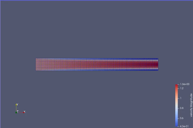
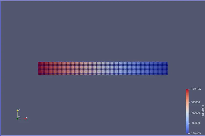
- Velocity and pressure contours for all the 3 base mesh sizes
- Show mesh (i.e surface with edges) for the 3 base mesh sizes
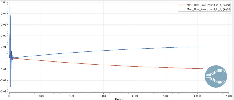
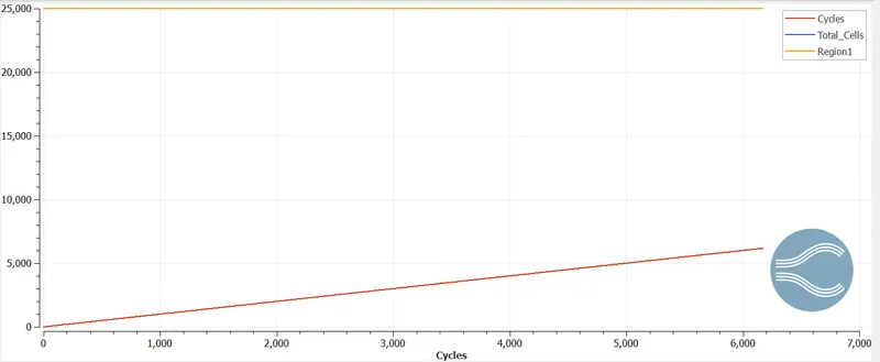
- Plots for velocity, pressure, mass flow rate, and total cell count for all 3 base mesh sizes.
- Explain the plots and write a detailed report on your project.
- Upload an animation to youtube and attach the link here using the add media option. Explain the development of the flow using the animation.
Make sure you make your project public. Once you are done, paste the link to your project here.
Theory Behind the challenge:
Here we have steady-state flow over a channel that basically has an inlet and outlet. And considering all the technical parameters we have the following theory about the channel flow.
A steady-state flow refers to the condition where the fluid properties at any point in a system do not change over time. These fluid properties include temperature, pressure, and velocity. One of the most significant properties that are constant in a steady-state flow system is the system mass flow rate. This means that there's no accumulation in mass within any component of the system.
This channel flow system here represents the same theory where all the parameters come into play when flow over a pipe. This is done as a simulation over time in 3 different programs to represent the different outcomes with the same base mesh.
Building up a case setup:
Now here we start by running the COnverge CFD software were building up a case setup of channel flow that represents the parameters to run the data.
To create geometry, select geometry icon<shape<box< the required dimension.
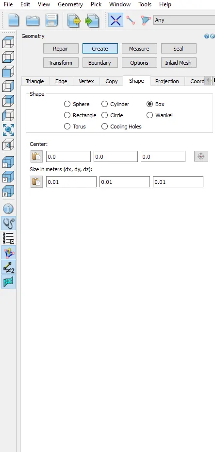
the required dimension be like
centre: 0.05, 0.0, 0.0
Size in metre (dx, dy, dz): 0.1 , 0.01, 0.01
along with boundaries to be assigned as INLET, OUTLET, WALLS, FRONT-BACK ends
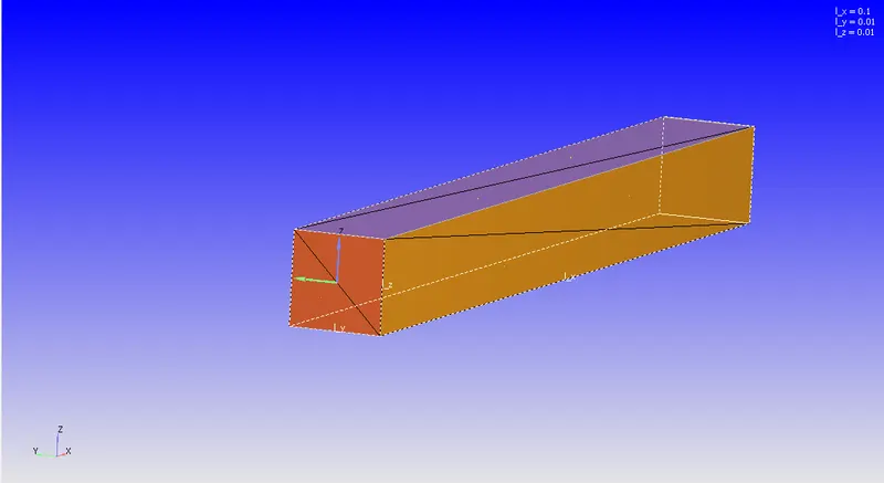
The geometry is set for the case setup now. Now the Assigning all types of Technical parameters for the flow property to case set up in the bottom right side. Below is the image is shown where all the case setup should like. The green tick indicates the all the parameter is set right according to flow properties.
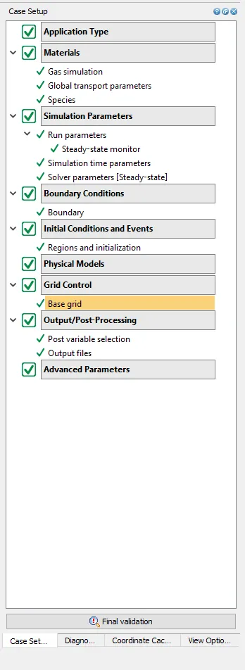
Before Jumping into the simulation part in Cygwin, one needs to set up the parameters in case set up to look like the above image. The value represents in the above image shows the completion of the properties, here's how every section needs to be done.
Application type:
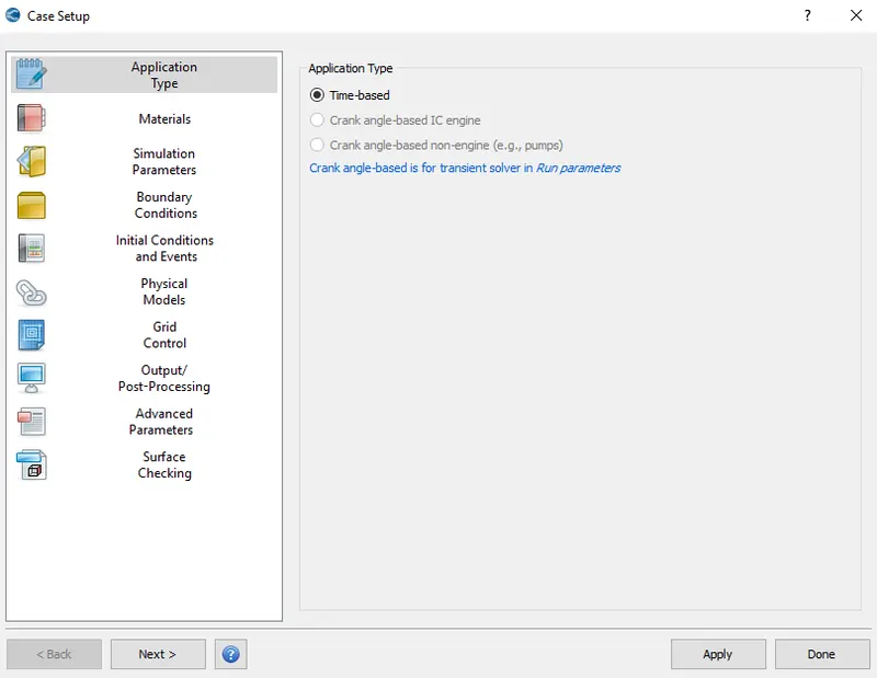
Selecting the Time-Based is the option available here as we are only setting up a simple channel flow profile, to begin with.
Materials:
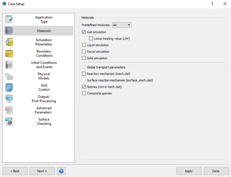
By selecting the predefined Mixture as AIR and checking Species.dat and gas simulation we complete materials setup.
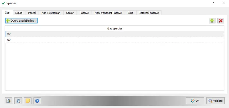
Moving on to another section we have SPECIES where we O2 and N2 in the gas.
Moving on to Another section called Run Parameters where we assign very important terms to proceed.
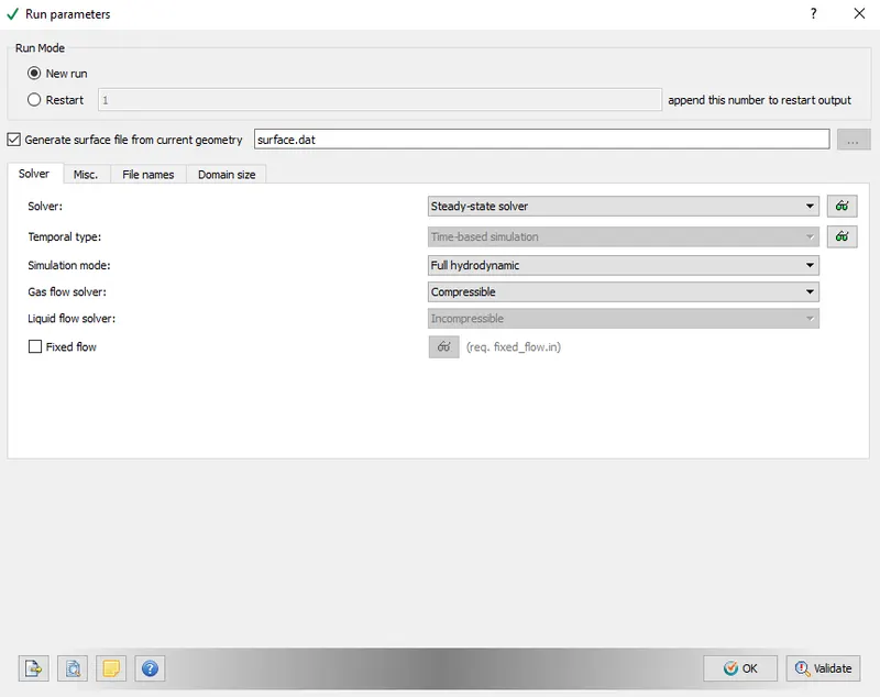
We select steady-state solver in the solver section and Full hydrodynamics in the solver section because we are going for simple channel flow. Where there is no complication in this system technically. The full hydrodynamic always take a lot of time to process the data files as it runs the basic Navier stokes equation through and through which might take a lot of time. Hydrodynamics would be a viable option here but again the fluid dynamics properties won't take place while running which is also not quite an option in some cases. SInce it's a simple flow Full hydrodynamics option can fully be considered and no complications would be three.
Followed by Solver we have the Misc. option where we select the steady-state here again including unchecking the used memory option as we don't want extra storage for the simulation.
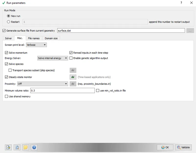
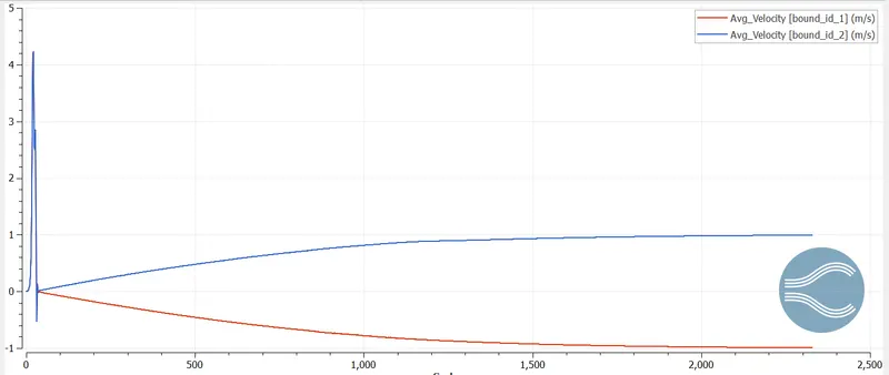
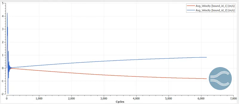
Moving onto the steady-state monitor we have a list selecting section where we ADD first and then select Avg velocity. Now, this is the section where we need those parameters that we need to display when getting the output. So here we need to know the avg velocity of the flow when it flows out of the channel in OUTLET. That's is why assigning the value to the parameter.
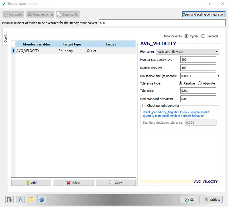
Assigning the value and validating it and Ok.
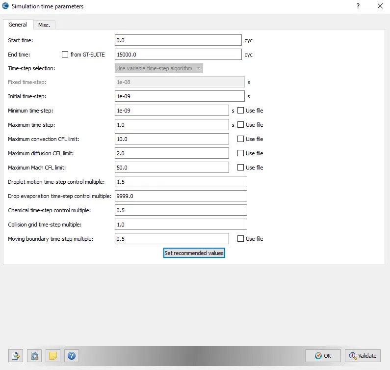
In another section called Simulation-Time Parametres here, we have all the values that are going to be involved in the simulation we are setting up.
The values here as follows for assigning. The end time is always 15000.
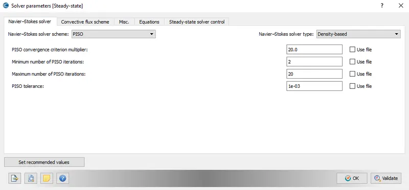
In the nest section of Solver-Parameters, we have what kind type of Navier-stokes solver, which is a Density-based solver for this flow.
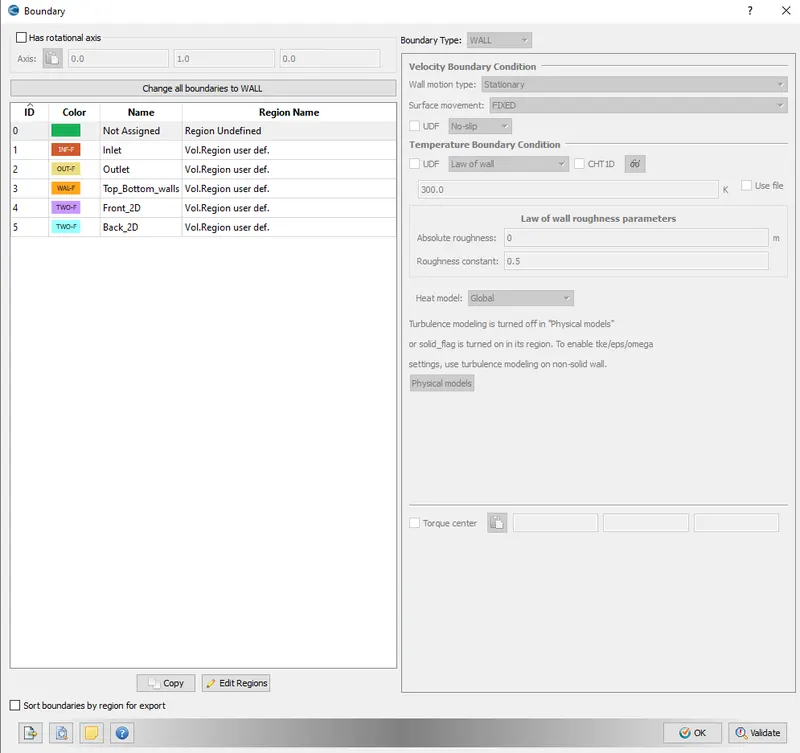
The next section is really important as we assign the Boundary condition for the flow and the walls around it to define the type of fluid flow effect on it while flowing.
INLET - Volumetric region user defined
OUTLET - Volumetric region user-defined
TOP-BOTTOM WALLS - Volumetric region user-defined
FRONT_2D- Volumetric region user-defined
BACK_2D - Volumetric region user-defined
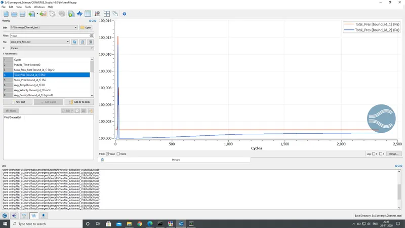
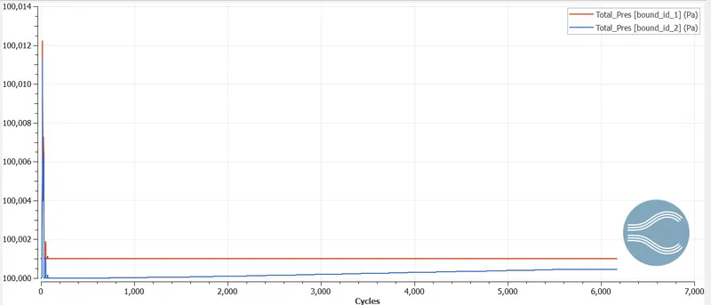
above is how we assign the properties along with section-wise with INLET PRESSURE 100001.0 Pa and OUTLET PRESSURE 100000.0 Pa with 300K temperature in temperature boundary conditions.
In the Region and Initialization, We need to add the O2 and N2 ratios for the flow.
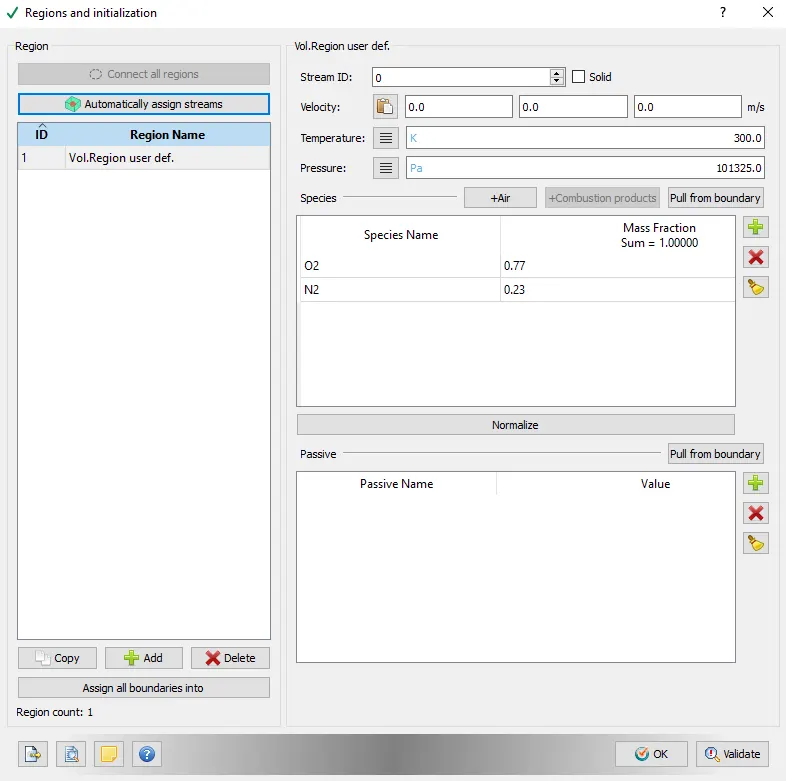
IN the Physical-Modelling We need to uncheck the turbulence modeling as there won no obstacle in a simple flow over a channel. To not complicate our simulation not adding extra features simplifies that.
Now the next section is Base Grid, where we assign the INPUT coordinated for the channel so that it has a different output for different inputs. This where the box we create in the first stem gets its own assigned values of coordinates in a cartesian lane.
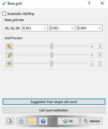
- dx = 2e-4m, dy = 2e-4m, dz = 2e-4m
- dx = 1.5e-4m, dy = 1.5e-4m, dz = 1.5e-4m
- dx = 1.0e-4m, dy = 1.0e-4m, dz = 1.0e-4m
These are the required inputs for the Base Mesh Grid for 3 different Outputs.
Next is Output files where the simulation through data files per cycle is determined. The timings per cycle here is really important as it shows the data files per cycle which are required to tun the smooth curve simulation and animation in ParaView. These are the input data that needs to be assigned here as below.
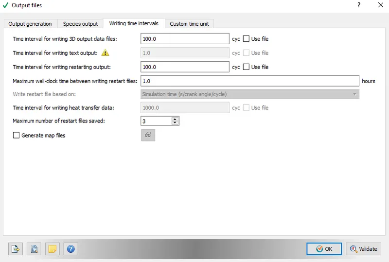
So here your wholes case setup is READY and we can proceed with Post process simulation in CYGWIN.
Post-Process Simulation (CYGWIN):
Run Cygwin go to the directory where we have our basic .dat files in the converge folder. These are the following commands in Cygwin to go to the directory
$ cd <where you have installed it>
and tun the following command to convert,dat files into 3d OUtput dat files.
$ mpiexec.exe -n 2 "the path where you have intelmpi.exe" restricted </dev/null> logfile &

This how to convert .dat files into 3d Output data files for post-processing.
after that, we need to convert those files so that ParaView can read it 3d output files. We need to do through Cygwin to convert those files too with the following command.
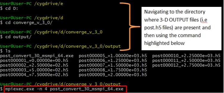
The Following outputs can be viewed In ParaView
OUTPUT POST-PROCESS:
- dx = 1.0e-3m, dy = 1.0e-3m, dz = 1.0e-3m
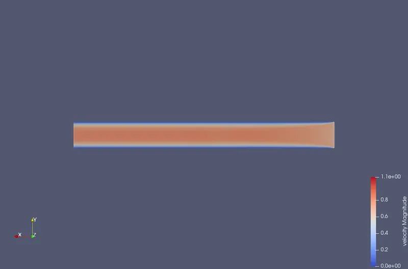
Velocity Contour
Pressure Contour:
Plotting :
Avg Velocity
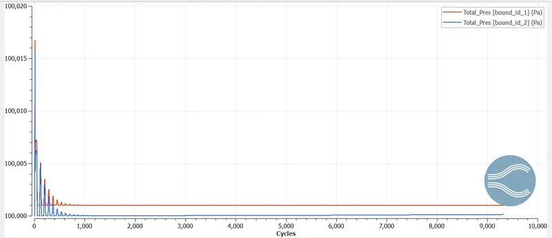
Total Pressure:
Mass-Flow rate:
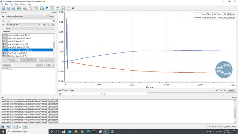
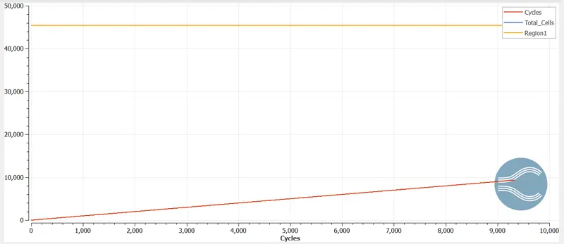
Total-Cell count:
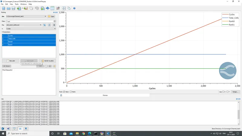
- dx = 2e-4m, dy = 2e-4m, dz = 2e-4m
Velocity Contour
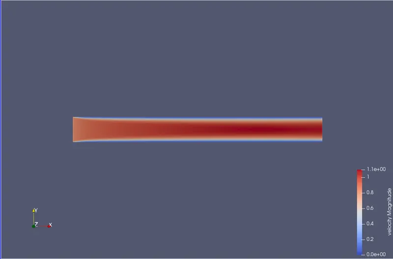
Pressure Contour
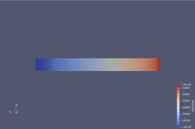
Plotting
Avg Velocity
Mass-flow rate
Total Pressure
Total cell count
- dx = 1.5e-4m, dy = 1.5e-4m, dz = 1.5e-4m
Velocity contour
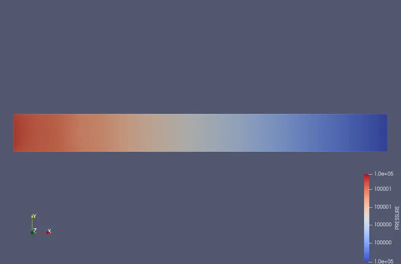
Pressure contour
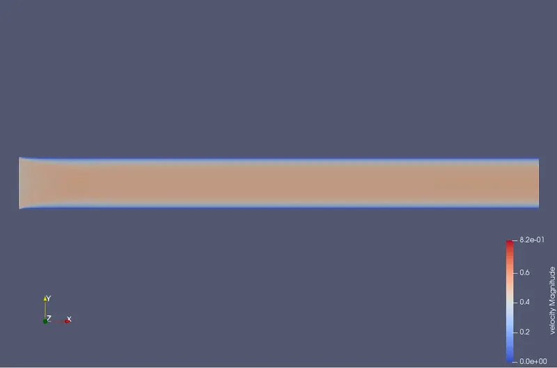
Avg Velocity
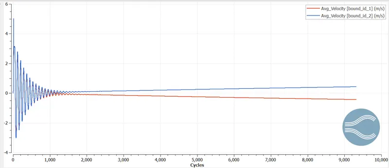
Mass-flow rate
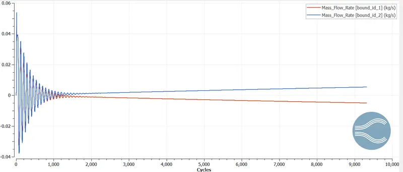
Total pressure
Cell count regions
- dx = 1.0e-4m, dy = 1.0e-4m, dz = 1.0e-4m
Velocity Contour:
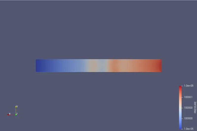
Pressure C0ntour
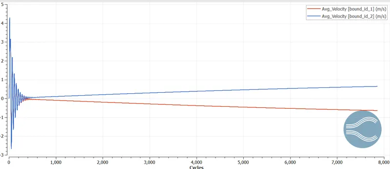
Avg Velocity
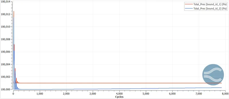
Total pressure
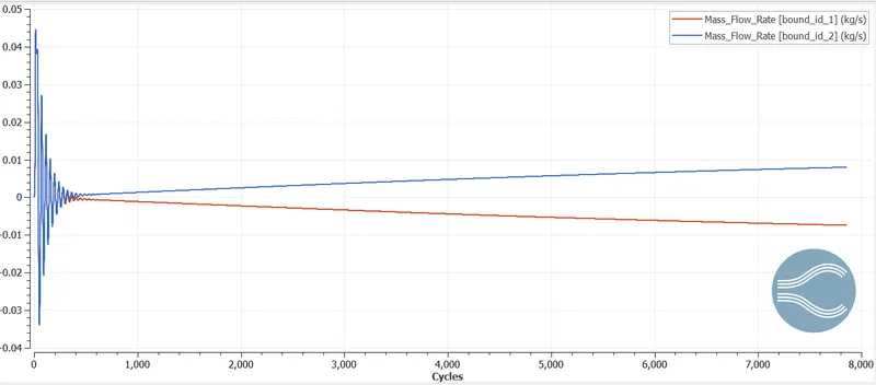
Mass-flow rate
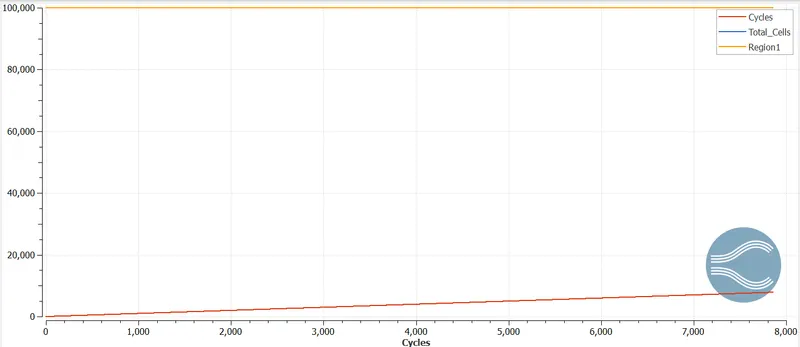
Total cell regions
References:
HOW TO RUN A SIMULATION IN CONVERGE v3.0? : Skill Lync (freshdesk.com)
Steady-State Flow - Fluid Flow Hydraulic and Pneumatic, EngineersEdge