Pipe Flow Simulation using OpenFOAM Part-I [Wedge BC]
Laminar Pipe Flow Simulation in OpenFOAM
Part-1 [Wedge Boundary condition]:
Objectives:
1) Calculating the pre-elementary properties related to the flow according to the Hagen-Poiseuille equation.
2) Creating the mesh script(blockMeshdict file) for specifying the geometry and boundary condition.
3) Creating a MATLAB program for automatically generating the blockMesh file for any wedge angle and grading scheme.
4) Comparing the simulation results with the analytical solution.
---------------------------------------------------------------------------------------------------------------------------------
Introduction:
In this project, we are trying to simulate the flow through a section of the pipe using a wedge boundary condition to understand the various aspects of flow through a pipe. The fluid used is water and the flow is laminar and incompressible we also neglect any changes in the cross-section. The Reynolds number is specified as 2100.
Fluid velocity changes from zero at the pipe boundary to the maximum at the center of the pipe due to the shear stress caused by the viscosity of the working fluid. To get this effect in the simulation we give a no-slip boundary condition at the pipe boundary. The average velocity remains constant in an incompressible flow if the cross-section remains constant.
We are trying to simulate the flow in accordance with the Hagen-Poiseuille Law i.e. a physical law that gives the pressure drop in an incompressible and Newtonian fluid in laminar flow flowing through a long cylindrical pipe of constant cross-section and there is no acceleration of fluid in the pipe.
Reynold's Number:
The transition from Laminar flow to Turbulent flow occurs from Laminar(`Re<=2100`) to Transition(`2100<=Re<=4000`) to Turbulent(`Re>4000`) for a smooth pipe with no viscous dissipation. It depends on the geometry, face roughness, flow velocity, surface temperature, etc. Reynold's is a dimensionless quantity used to help predict flow patterns in different fluid flow situations, which is calculated as the ratio of the Inertia force to Viscous force an is expressed for internal flow in a circular pipe as:
`Re = (rho*V_(avg)*D)/mu`
where,
`rho` is density
D is the diameter of the pipe
`V_(avg` is the average velocity in the pipe
`mu` is the dynamic viscosity
Hydrodynamic entry Length:
The entrance length is the distance a flow travels after entering a pipe before the flow becomes fully developed. Entrance length refers to the length of the entry region, the area following the pipe entrance where effects originating from the interior wall of the pipe propagate into the flow as an expanding boundary region. When the boundary layer expands to fill the entire pipe, the developing flow becomes a fully developed flow, where flow characteristics no longer change with increased distance along the pipe.
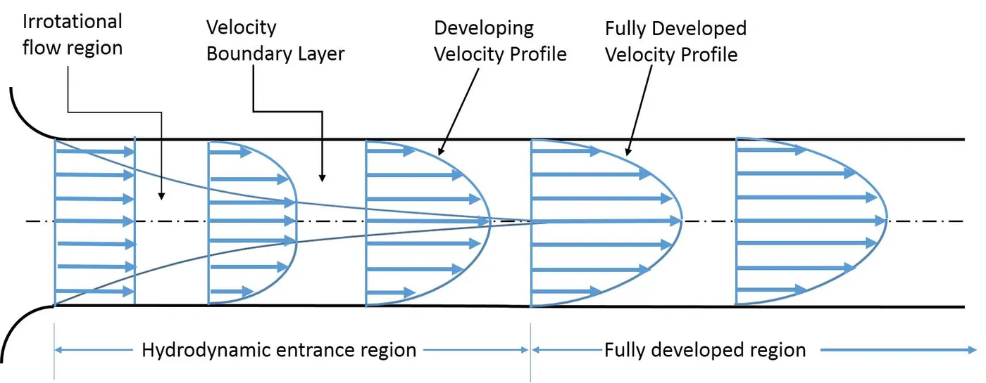
Shear Stress:
In the hydrodynamic entrance region, the wall shear stress (τw ) is highest at the pipe inlet, where the boundary layer thickness is the smallest. Shear stress decreases along the flow direction. That is why the pressure drop is highest in the entrance region of a pipe, which increases the average friction factor for the whole pipe. This increase in the friction factor is negligible for long pipes.
In a fully developed region, the pressure gradient and the shear stress are in balance.
Velocity profile for Laminar flow:
The velocity profile for a fully developed laminar flow is parabolic with the maximum at the center line and minimum at the R=0.
By doing a force balance on a small volume element in the fully developed flow region in the pipe (Laminar Flow), we get velocity as a function of radius only i.e. it does not depend upon the axial distance from the entry point. The velocity as the function of radius comes out to be:
`u(r) = R^2/(4*mu) *((dP)/(dx))*(1-(r^2)/R^2)`
where `(dP)/(dx)` is constant.
r is the distance from the center where we have considered the volume element.
R is the radius of the pipe.
`mu` is the dynamic viscosity.
The average velocity can be written as `V_(avg ) = R^2/(8*mu) *((dP)/dx)`
hence the equation becomes `u(r)=2*V_(avg)*(1-r^2/R^2)`
For a fully developed flow, the maximum velocity will be at r=0.
Thus,

According to the Hagen-Poiseuille law
Flowrate: `Q=V_(avg)*A_c = (DeltaP*pi*D^4)/(128*mu*L`
Average Velocity : `V_(avg) = (DeltaP*D^2)/(32*mu*L)`
Specifications of the Problem:
1) Given Reynold's number = 2100
2) The working fluid is water at 25 degrees Celcius
3) The diameter of the pipe = 0.02 m
4) The entry length is `L_(entry) = 0.06*Re*D or L_(entry) = 2.52m`
5) The length of the pipe for this simulation is taken as 2.7 m
6) The density of water `rho=997kgm^-3`
7) The dynamic viscosity of water `mu = 0.89xx10^-3Pa.S`
8) The kinematic viscosity of water `nu = 0.8972xx10^-6 m^2s^-1`
Calculated Values: (Analytical Solution)
1) Average Velocity `V_(avg) =(R*mu)/(rho*D) =0.09373ms^-1`
2) Maximum Velocity `V_(max) = 2*V_(avg) = 0.1875ms^-1`
3) Pressure Drop `DeltaP =(32*mu*L*V_(avg))/D^2 =18.01 Pa`
4) Kinematic pressure drop `Deltap_k = (DeltaP)/rho =0.018072 m`
MATLAB Program:
A MATLAB program was written to generate the blockMesh file for OpenFOAM.
clear all
close all
clc

%% MATLAB program for auto-generation of blockmesh file in OpenFoam %%

L = 2.7;# length of pipe
d = 0.02; # diameter
r = d/2; # radius
theta = 2; # degree(input according to the need)

%% Calculating the vertices of the wedge
v0 = [ 0 0 0 ];
v1 = [ 0 r*cosd(theta/2) -r*sind(theta/2) ];
v3 = [ 0 r*cosd(theta/2) r*sind(theta/2) ];
v4 = [ L 0 0 ];
v5 = [ L r*cosd(theta/2) -r*sind(theta/2) ];
v6 = [ L r*cosd(theta/2) r*sind(theta/2) ];

%% String format specifying for Blockmesh file %%

head1 = "/*--------------------------------*- C++ -*----------------------------------*";
head2 = "  =========                 |                                                 ";
head3 = "  \      /  F ield         | OpenFOAM: The Open Source CFD Toolbox            ";
head4 = "   \    /   O peration     | Website:  https://openfoam.org                   ";
head5 = "    \  /    A nd           | Version:  6                                      ";
head6 = "     \/     M anipulation  |                                                  ";
head7 = "*---------------------------------------------------------------------------*/";

b4 = blanks(4);
b8 = blanks(8);
b12 = blanks(12);
b16 = blanks(16);

dict1 = "    version     2.0;";
dict2 = "    format      ascii;";
dict3 = "    class       dictionary;";
dict4 = "    object      blockMeshDict;";
dict5 = "// * * * * * * * * * * * * * * * * * * * * * * * * * * * * * * * * * * * * * //";

conv = "convertToMeters 1;";

vertex1 = "vertices";

blocks1 = "hex (0 1 2 0 3 4 5 3) (50 1 200) simpleGrading (0.2 1 1)";

footer = "// ************************************************************************* //";

%% Creting blockMesh dict for OepnFOAM %%

f1 = fopen('blockMeshdict.txt','w')

% Printing the headder %%

fprintf(f1,'%s\r\n' ,head1);
fprintf(f1,'%s\r\n' ,head2);
fprintf(f1,'%s\r\n' ,head3);
fprintf(f1,'%s\r\n' ,head4);
fprintf(f1,'%s\r\n' ,head5);
fprintf(f1,'%s\r\n' ,head6);
fprintf(f1,'%s\r\n' ,head7);

fprintf(f1,'FoamFile\r\n{\r\n' );

fprintf(f1,'%s%s\r\n', b4,dict1);
fprintf(f1,'%s%s\r\n', b4,dict2);
fprintf(f1,'%s%s\r\n', b4,dict3);
fprintf(f1,'%s%s\r\n}\r\n', b4,dict4);
fprintf(f1,'%s%s\r\n', b4,dict5);

fprintf(f1,'%s\r\n', conv);

%% Printing the vertices %%

fprintf(f1,'vertices\r\n(\r\n');
fprintf(f1,'%s(%d %d %d)\r\n', b4,v0(1),v0(2),v0(3));
fprintf(f1,'%s(%d %f %f)\r\n', b4,v1(1),v1(2),v1(3));
fprintf(f1,'%s(%d %f %f)\r\n', b4,v3(1),v3(2),v3(3));
fprintf(f1,'%s(%f %d %d)\r\n', b4,v4(1),v4(2),v4(3));
fprintf(f1,'%s(%f %f %f)\r\n', b4,v5(1),v5(2),v5(3));
fprintf(f1,'%s(%f %f %f)\r\n', b4,v6(1),v6(2),v6(3));
fprintf(f1,');\r\n');

%% Printing the blocks %%

fprintf(f1,'\r\nblocks\r\n(\r\n');
fprintf(f1,'%s%s\r\n', b4,blocks1);
fprintf(f1,');\r\n');

%% Printing edges %%

fprintf(f1,'\r\nedges\r\n(\n');
fprintf(f1,'%sarc 1 2 (0 %0.3f 0)\r\n', b4,r);
fprintf(f1,'%sarc 4 5 (%0.2f %0.3f 0)\r\n', b4,L,r);
fprintf(f1,');\r\n');

%% Printing boundary %%

fprintf(f1,'\r\nboundary\r\n(\r\n');
fprintf(f1,'%saxis\n%s{\r\n', b4,b4);
fprintf(f1,'%stype empty;\r\n', b8);
fprintf(f1,'%sfaces\n%s(\r\n', b8,b8);
fprintf(f1,'%s(0 3 3 0)\r\n%s);\r\n%s}\r\n', b12,b8,b4);

fprintf(f1,'%sinlet\r\n%s{\r\n', b4,b4);
fprintf(f1,'%stype patch;\r\n', b8);
fprintf(f1,'%sfaces\r\n%s(\r\n', b8,b8);
fprintf(f1,'%s(0 2 1 0)\r\n%s);\r\n%s}\r\n', b12,b8,b4);

fprintf(f1,'%swall\r\n%s{\r\n', b4,b4);
fprintf(f1,'%stype wall;\r\n', b8);
fprintf(f1,'%sfaces\r\n%s(\r\n', b8,b8);
fprintf(f1,'%s(2 5 4 1)\r\n%s);\r\n%s}\r\n', b12,b8,b4);

fprintf(f1,'%soutlet\r\n%s{\r\n', b4,b4);
fprintf(f1,'%stype patch;\r\n', b8);
fprintf(f1,'%sfaces\r\n%s(\r\n', b8,b8);
fprintf(f1,'%s(3 4 5 3)\r\n%s);\r\n%s}\r\n', b12,b8,b4);

fprintf(f1,'%sfront\r\n%s{\r\n', b4,b4);
fprintf(f1,'%stype wedge;\r\n', b8);
fprintf(f1,'%sfaces\r\n%s(\r\n', b8,b8);
fprintf(f1,'%s(0 3 5 2)\r\n%s);\r\n%s}\r\n', b12,b8,b4);

fprintf(f1,'%sback\r\n%s{\r\n', b4,b4);
fprintf(f1,'%stype wedge;\r\n', b8);
fprintf(f1,'%sfaces\r\n%s(\r\n', b8,b8);
fprintf(f1,'%s(0 1 4 3)\r\n%s);\r\n%s}\r\n);\r\n', b12,b8,b4);

fprintf(f1,'\r\nmergePatchPairs\r\n(\r\n);\r\n');

fprintf(f1,'%s', footer);

fclose(f1)
The code is used to generate the blockMesh file for wedge angles(2,3,4).
Following is the blockMesh file for a wedge of angle 2 degrees:
/*--------------------------------*- C++ -*----------------------------------*
  =========                 |
  \      /  F ield         | OpenFOAM: The Open Source CFD Toolbox
   \    /   O peration     | Website:  https://openfoam.org
    \  /    A nd           | Version:  6
     \/     M anipulation  |
*---------------------------------------------------------------------------*/
FoamFile
{
    version     2.0;
    format      ascii;
    class       dictionary;
    object      blockMeshDict;
}
// * * * * * * * * * * * * * * * * * * * * * * * * * * * * * * * * * * * * * //

convertToMeters 1;

vertices
(
    (0 0 0)
    (0 0.0099985 -0.00017452)
    (0 0.0099985 0.00017452)
    (2.7 0 0)
    (2.7 0.0099985 -0.00017452)
    (2.7 0.0099985 0.00017452)
);

blocks
(
    hex (0 1 2 0 3 4 5 3) (50 1 200) simpleGrading (0.2 1 1)
);

edges
(
    arc 1 2 (0 0.01 0)
    arc 4 5 (2.7 0.010 0)
);

boundary
(
    axis
    {
        type empty;
        faces
        (
            (0 3 3 0)
        );
    }
    inlet
    {
        type patch;
        faces
        (
            (0 2 1 0)
        );
    }
    wall
    {
        type wall;
        faces
        (
            (2 5 4 1)
        );
    }
    outlet
    {
        type patch;
        faces
        (
            (3 4 5 3)
        );
    }
    front
    {
        type wedge;
        faces
        (
            (0 3 5 2)
        );
    }
    back
    {
        type wedge;
        faces
        (
            (0 1 4 3)
        );
    }
);

mergePatchPairs
(
);

// ************************************************************************* //
Boundary Condition:
Here a velocity inlet and pressure outlet boundary condition is being used.
Velocity -
/*--------------------------------*- C++ -*----------------------------------*\
  =========                 |
  \\      /  F ield         | OpenFOAM: The Open Source CFD Toolbox
   \\    /   O peration     | Website:  https://openfoam.org
    \\  /    A nd           | Version:  6
     \\/     M anipulation  |
\*---------------------------------------------------------------------------*/
FoamFile
{
    version     2.0;
    format      ascii;
    class       volVectorField;
    object      U;
}
// * * * * * * * * * * * * * * * * * * * * * * * * * * * * * * * * * * * * * //

dimensions      [0 1 -1 0 0 0 0];

internalField   uniform (0.09373 0 0);

boundaryField
{
    axis
    {
        type            empty;
    }

    inlet
    {
        type            fixedValue;
        value           uniform (0.09373 0 0);
    }

    wall
    {
        type            fixedValue;
        value           uniform (0 0 0);
    }
    outlet
    {
        type            zeroGradient;
    }
    front
    {
        type            wedge;
    }
    back
    {
        type            wedge;
    }
}

// ************************************************************************* //
Pressure boundary condition:
/*--------------------------------*- C++ -*----------------------------------*\
  =========                 |
  \\      /  F ield         | OpenFOAM: The Open Source CFD Toolbox
   \\    /   O peration     | Website:  https://openfoam.org
    \\  /    A nd           | Version:  6
     \\/     M anipulation  |
\*---------------------------------------------------------------------------*/
FoamFile
{
    version     2.0;
    format      ascii;
    class       volScalarField;
    object      p;
}
// * * * * * * * * * * * * * * * * * * * * * * * * * * * * * * * * * * * * * //

dimensions      [0 2 -2 0 0 0 0];

internalField   uniform 0;

boundaryField
{
    axis
    {
        type            empty;
    }

    inlet
    {
        type            zeroGradient;
    }

    wall
    {
        type            zeroGradient;
    }
    outlet
    {
        type            fixedValue;
        value           uniform 0.018072;
    }
    front
    {
        type            wedge;
    }
    back
    {
        type            wedge;
    }
}

// ************************************************************************* //
Transport Properties:
/*--------------------------------*- C++ -*----------------------------------*\
  =========                 |
  \\      /  F ield         | OpenFOAM: The Open Source CFD Toolbox
   \\    /   O peration     | Website:  https://openfoam.org
    \\  /    A nd           | Version:  6
     \\/     M anipulation  |
\*---------------------------------------------------------------------------*/
FoamFile
{
    version     2.0;
    format      ascii;
    class       dictionary;
    location    "constant";
    object      transportProperties;
}
// * * * * * * * * * * * * * * * * * * * * * * * * * * * * * * * * * * * * * //

nu              [0 2 -1 0 0 0 0] 1e-6;


// ************************************************************************* //
Mesh Profile:
Wedge Boundary Condition:
The wedge boundary condition defines an axis-symmetric boundary condition. The model and flow must be axis-symmetric along a central line such that all physical variables of the flow have the same value and distribution at a radius and angle.
The axis-symmetric ‘wedge’ boundary is specified by two planes that must be selected on separate sides of the domain on surfaces running along the central line.
Simulation Results:
[Wedge Angle = 2 degrees]
Velocity profile at the time - 1.25
Velocity profile at the time - 25
Velocity profile curves:
At distance 0.01 m from inlet -
The velocity is nearly rectangular at the inlet and it gradually attains a parabolic profile as the flow becomes fully developed which will be evident from the velocity curves shown below.
Before the boundary layers from the periphery meet at the axis, there prevails a core region which is uninfluenced by viscosity.
Since the volume-flow must be the same for every section and the boundary-layer thickness increases in the flow direction, the inviscid core accelerates, and there is a corresponding fall in pressure.
At inlet:
1. The velocity gradient is steeper at the wall, causing a higher value of shear stress as compared to a developed flow.
2. Momentum flux across any section is higher than that typically at the inlet due to the change in the shape of the velocity profile.
3. Arising out of these, an additional pressure drop is brought about at the entrance region as compared to the pressure drop in the fully developed region.
At distance 0.2 m from the inlet -
At distance 0.5 m from inlet -
At distance 1 m from inlet -
The entry length Calculated analytically is `L_(entry) =2.52m` from the inlet where the flow will be fully developed -
Shear Stress Plot for a fully developed region:
The steps incrementation is due to the fact that the grid is not fine enough at the center of the pipe but as we move to the pipe boundary we can see that the magnitude to the steps decreases which is the indication that the grid is much finer at the pipe walls.
Velocity profiles for other wedge angles:
WEDGE ANGLE - 3 degrees
Mesh Profile:
Velocity near the inlet:
Velocity fully developed:
Velocity curve at 0.1 m from inlet:
Velocity curve at 2.52 m from inlet:
WEDGE ANGLE - 4
Mesh Profile -
Velocity near inlet:
Velocity fully developed:
Velocity curves at 0.1 m from inlet:
Velocity curve at 2.52 m from inlet:
Comparison of Simulation results:
In the below table we are comparing the maximum velocity obtained from the simulation for different wedge angles with the analytically calculated value using the Hagen-Poiseuille equation -
The max velocity in the case of simulation is calculated at 2.52 m from the inlet which is the entry length for this case.