Meshing Hood for Structural Analysis And Using Hemming process
OBJECTIVE :
- Perform geometry clean up of HOOD and mesh the model for structural analysis.
- Target element size of 5mm.
- To create the mid surface of the model.
- Mesh show in shell mode.
- To carry out the hemming process.
PROCEDURE: As the HOOD model, we can create a mid surface of it of the inner part of the hood and outer part of hood and then stitch them together.
FIG.1 QUALITY CRITERIA SHEET
In the above fig, there are quality criteria by which we have to define the quality of all the models
FIG.2 ENT MODE SHOWING MISSING SURFACE AND TOPO ERRORS
- As the model is open we can see the HOOD surface which has lots of missing surfaces and extra surface we should get rid of them by using the TOPO command and the surface which are not correct by the topo mode that should be deleted and recreated.
- So at the time, we are doing the topo and error elimination, when its finished go for geometry check there are unchecked surfaces.
- This unchecked surface can be eliminated by manual and by auto-fix mode.
- But first, go for manual where we are facing error and then go for the auto fix as it can save time.
FIG.3 ENT MODE MISSING SURFACE AND TOPO ERRORS ARE REMOVED
- check the thickness of the surface, for which we need to create the mid surface
- As the surface thickness is around 0.75
- Mid surface will be at the center of the plane so it should be half pf the distance between the two nodes
FIG.4 THICKNESS OF THE HOOD INNER SURFACE OR THE DISTANCE BETWEEN THE TWO NODES
- By using the mid-surface or offset command or the middle we can create the mid surface of the surface
- We use the offset command for the inner surface and create the mid surface.
- Use OFFSET VALUE as -0.75/2 as the offset is created on the opposite side.
FIG.5 USING OF OFFSET COMMAND
- By middle-click we get the mid surface created and we can see the mid surface by hiding the geometry and we should not delete the original surface that we will require for reference.
- Perform geometry check and ignore the single cons.
- There are needle faces created auto-fix them.
FIG.6 MID-SURFACE IS CREATED OF INNER HOOD
- As the geometry is symmetry we can create the mesh for the half and create a copy of that and mesh another part again.
- For that use project cut for making symmetry.
- As the geometry is symmetry or not to check to use a command called RMDL. this checks whether the geometry is symmetry or not if not shos an error.
FIG.7 CHECKING WHETHER THE SYMMETRY IS PROPER OR NOT
- As the geometry is not symmetry over some surface we need to make symmetry.
- By deleting the half surface and saving another surface and make a copy of that and remesh them.
- Do mesh for the first part and then by hiding the mesh part and delete the half surface.
FIG.8 DELETING THE SYMMETRY SURFACE AND MAKING COPY AND MESHING BOTH THE SURFACE
- As the mid surface of the inner part of the HOOD is created.
- We can move to the hood body.
FIG.9 CREATING MIDSURFACE BY USING MIDDLE SURFACE (SKIN) COMMAND
- For this, we will use a new command called middle-surface (skin).
- SKIN SURFACE will create a mid surface of the HOOD.
FIG.10 MIDSURFACE CREATED SEEN BY RED CONS
- By selecting the hatch of the midsurface we can see the mid surface.
- We have successfully created a mid surface.
- As we can see the red-cons outer surface is created as mid surface.
FIG.11 MIDSURFACE OF OUTER HOOD CREATED
- Define the PIDS for the outer and inner surface.
- Delete the PIDs not required.
- Show the visible.
- Now we need to go for a hemming process.
FIG.12 PIDS SETUP FOR INNER AND OUTER HOOD
FIG.13 PID MODE VISIBLE PARTS ARE SHOWN
HEMMING PROCESS :
Hemming is a forming operation in which the edges of the sheet are folded or folded over another part in order to achieve a tight fit. Normally hemming operations are used to connect parts together, to improve the appearance of a part and to reinforce part edges.
In-car part production, hemming is used in assembly as a secondary operation after deep drawing, trimming and flanging operations to join two sheet metal parts (outer and inner) together. Typical parts for this type of assembly are hoods, doors, trunk lids, and fenders.
The accuracy of the hemming operation is very important since it affects the appearance of the surface and surface quality. Material deformations, which occur during the hemming process, can lead to dimensional variations and other defects in parts. Typical hemming defects are splits or wrinkles in the flange, material overlaps in the corner areas or material roll-in. This is why it is important to use simulation tools in order to, on the one hand, better understand the hemming process and, on the other hand, significantly reduce the number of “trial and error” loops during tryout and production.
There are various types of hemming operations:
- Conventional die hemming
- Roll hemming
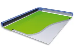
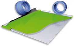
Conventional die hemming
Conventional die hemming is suitable for mass production. In die hemming, the flange is folded over the entire length with a hemming tool. Normally the actual hemming is a result of a forming operation in which the flange is formed with a hemming tool after the drawing and trimming operations have been completed. The formed flange is then hemmed in several process steps. These steps include, for example, the pre-hemming and final hemming depending on the respective opening angle of the flange. Production plants for conventional die hemming are very expensive, but the cycle times are very low.
Roll hemming
Roll hemming is carried out incrementally with a hemming roller. An industrial robot guides the hemming roller and forms the flange. Roll hemming operation can also be divided into several pre-hemming and final hemming process steps. Roll hemming is very flexible to use and tool costs are significantly lower as compared to those of conventional die hemming. However, the cycle times are much higher since the hemming is realized using a hemming roller which follows a defined path.
A hemming process in which the mid surface are been stitched to each other.
- As both the surface are visible we need to start the humming process
- For that first project the surface over of hood outer over itself.
- And delete surface which is not required like the side body of the outer body.
- by all the sides as a loop, we need to project.
FIG.14 CONS PROJECTED TO THE SURFACE USING PROJECT CONS
- Projection is been see in the figure
- projected outer can be deleted as to we don't require for the hemming process
- As the borders of the outer body is been deleted.
- We can start the hemming process by joining.
- delete the hot points which are not required and which will create problems for the hemming process.
- create hot-points between the mid surface of the inner hood and outer hood.
PASTING OF CONS OF INNER AND OUTER SURFACE TO EACH OTHER
- By pasting the midset the cons of the inner and outer hood it turns into triple cons.
There are two surface stitching and triple cons are generated.
FIG.15 HEMMING PROCESS IS DONE
CONCLUSION:
- The mid surface of both the inner hood and outer hood is created.
- Geometry check is been carried out.
- Inner and outer mid surface are been stitched by hemming process.
- all extra surface is deleted.