IcoFOAM solver to simulate the flow through a backward-facing step
Objective: Study of icoFOAM solver to simulate the flow through a backward-facing step. You shall create different meshes and compare the results obtained from them.
Specification
The number of cells along the direction of flow = 200
The number of cells along the y-direction for each block = 10
Inlet Velocity is 1 m/sec.
Run the first simulation without grading factor.
Run the second simulation with the mesh grading factors of 0.2, 0.5 & 0.8. Compare the effect of grading factor with necessary contours & plots.
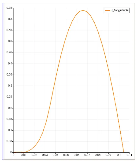
Measure the velocity profile at 0.085 m from the inlet of the geometry with a line plot.
Compare velocity magnitude contours near the step region for the above-mentioned grading factors.
Theory:
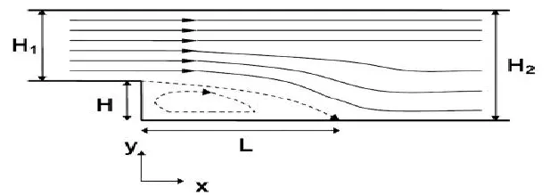
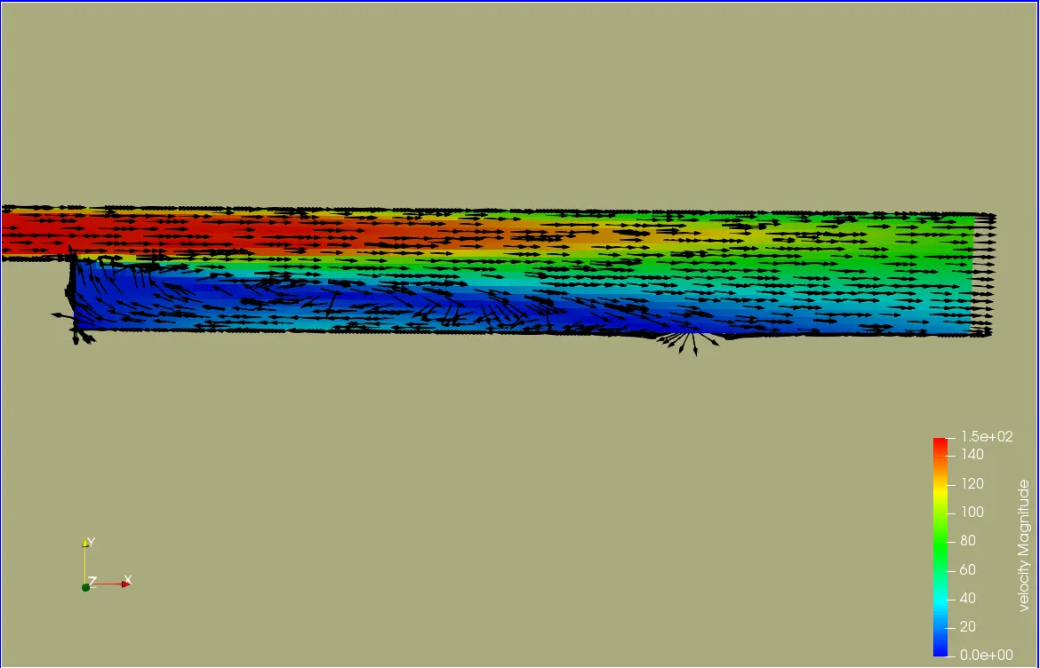
From the above figure, we can see that, at the edge of the step, the fluid boundary layer separates due to the sudden variation in the geometry which causes the fluid to lose some of its kinetic energy which turns the pressure gradient positive causing a free-shear layer to develop inside the original shear layer. The free shear originates due to high velocity on the top of the fluid in comparison to the momentum in the wake of the step. Continuous retardation of the flow turns the wall shear stress negative and the flow reverses and a region of recirculating occurs behind the step which is mostly responsible for the creation of unsteady eddy structure. The flow bubble/recirculation is driven by the low pressure created by the presence of vortices in the separated shear layer. Finally, as the fluid recovers from the sudden expansion, the pressure gradient becomes favorable and the fluid attaches at a position called reattachment point. However, the reattachment(separation) point is an unsteady phenomenon due to the presence of flapping(vortex sheddings). Therefore, to account for the unsteadiness the reattachment point is extended toward the streamwise direction which is known as the reattachment(separation) zone. The skin friction coefficient at the reattachment zone is zero due to its proportional relationship with the velocity gradient.
Ahead of the reattachment zone, the fluid-stream, which has some velocity of the free-stream, propagates forward.
Velocity distribution after flow separation over a horizontal distance
Equations use:
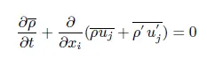
The continuity equation in conservation form represented. The first term in this equation describes the change in density with variation in time and the remaining three terms describes the net flow across the control volume.
The procedure of simulation as follows:
1. Use the icoFoam solver in openFoam to solve the floe using backward facing step. Copy the cavity folder under tutorial->incompressible->icoFam and paste it inside the $FOAM_RUN folder.
2. Edit the blockMeshDict file in the system folder with required vertices and grading factor.
3. Edit the initial boundary condition of P and U in system folder.
4. Run the blockMesh command in the terminal.
5. Run the icoFoam solver in the terminal.
6. Velocity profile can be plotted using plot over line tool.
BLOCKMESH PROCEDURE:
1. To create a Geometry we need to edit the blockMeshDict file that is available in the system folder.
2. Creating a boundary using 5 blocks as shown below.
3. Start indexing the vertices from 0.
4. Finally, to define the box we need to specify the right order of vertex indices. For example, to create the first box,
MESHING:
Now to mesh the geometry , we need to fill in the number of cells in x, y and z direction inside the second paranthesis of the Hex command.
i.e hex (0 1 2 3 11 12 13 14) (80 10 1) simpleGrading (0.2 0.2 1)
hex (3 2 4 5 14 13 15 16) (80 10 1) simpleGrading (0.2 0.2 1)
hex (2 7 6 4 13 18 17 15) (120 10 1) simpleGrading (0.2 0.2 1)
hex (1 8 7 2 12 19 18 13) (120 10 1) simpleGrading (0.2 0.2 1)
hex (10 9 8 1 21 20 19 12) (120 10 1) simpleGrading (0.2 0.2 1)
To refine the mesh near the wall of the geometry, we have assigned the few Grading factors in the third paranthesis.
BBOUNDARY CONDITIONS:
Befor we run the simulation we need to specify the Boundary conditions, the given boundary conditions are
1. Inlet (patch type)
The faces that contribute to inlet bounadry are shown above. If we are looking at these faces from the outside, the definition of ilet boundary will be in counter-clockwise direction.
(0 11 14 3)
(3 14 16 5)
2.Outlet (patch type)
Similarily, we have 3 faces contributing to the outlet bundary conditions.
(9 8 19 20)
(8 7 18 19)
(7 6 17 18)
3. Front and back (type empty)
(0 3 2 1)
(3 5 4 2)
(10 1 8 9)
(1 2 7 8)
(2 4 6 7)
4. No slip walls (type wall)
(16 15 4 5)
(15 17 6 4)
(10 21 12 1)
(11 0 1 12)
(21 10 9 20)
The blockMeshdict file for GRADING FACTOR 0.2
/*--------------------------------*- C++ -*----------------------------------*
  =========                 |
        /  F ield         | OpenFOAM: The Open Source CFD Toolbox
       /   O peration     | Website:  https://openfoam.org
      /    A nd           | Version:  7
     /     M anipulation  |
*---------------------------------------------------------------------------*/
FoamFile
{
    version     2.0;
    format      ascii;
    class       dictionary;
    object      blockMeshDict;
}
// * * * * * * * * * * * * * * * * * * * * * * * * * * * * * * * * * * * * * //

convertToMeters 1;

vertices
(
    (0 0 0)
    (0.08 0 0)
    (0.08 0.01 0)
    (0 0.01 0)
    (0.08 0.02 0)
    (0 0.02 0)
    (0.2 0.02 0)
    (0.2 0.01 0)
    (0.2 0 0)
    (0.2 -0.01 0)
    (0.08 -0.01 0)
    (0 0 0.1)
    (0.08 0 0.1)
    (0.08 0.01 0.1)
    (0 0.01 0.1)
    (0.08 0.02 0.1)
    (0 0.02 0.1)
    (0.2 0.02 0.1)
    (0.2 0.01 0.1)
    (0.2 0 0.1)
    (0.2 -0.01 0.1)
    (0.08 -0.01 0.1)
);

blocks
(
    hex (0 1 2 3 11 12 13 14) (80 10 1) simpleGrading (0.2 0.2 1)
    hex (3 2 4 5 14 13 15 16) (80 10 1) simpleGrading (0.2 0.2 1)
    hex (2 7 6 4 13 18 17 15) (120 10 1) simpleGrading (0.2 0.2 1)
    hex (1 8 7 2 12 19 18 13) (120 10 1) simpleGrading (0.2 0.2 1)
    hex (10 9 8 1 21 20 19 12) (120 10 1) simpleGrading (0.2 0.2 1)

 );

edges
(
);

boundary
(
    inlet
    {
        type patch;
        faces
        (
            (0 11 14 3)
            (3 14 16 5)
        );
    }
    outlet
    {
        type patch;
        faces
        (
            (9 8 19 20)
            (8 7 18 19)
            (7 6 17 18)
        );
    }
    frontandback
    {
        type empty;
        faces
        (
            (0 3 2 1)
            (3 5 4 2)
            (10 1 8 9)
            (1 2 7 8)
            (2 4 6 7)
        );
    }
      Noslipwall
    {
        type wall;
        faces
        (
            (16 15 4 5) //top_left
            (15 17 6 4)  //top_right
            (10 21 12 1)  //step_side
            (11 0 1 12)     //bottom_of_1
            (21 10 9 20)      //bottom_of_5
        );
    }
);

mergePatchPairs
(
);


// ************************************************************************* //
BLOCKMESH FOR GRADING FACTOR 0.5
hex (0 1 2 3 11 12 13 14) (80 10 1) simpleGrading (0.5 0.5 1)
hex (3 2 4 5 14 13 15 16) (80 10 1) simpleGrading (0.5 0.5 1)
hex (2 7 6 4 13 18 17 15) (120 10 1) simpleGrading (0.5 0.5 1)
hex (1 8 7 2 12 19 18 13) (120 10 1) simpleGrading (0.5 0.5 1)
hex (10 9 8 1 21 20 19 12) (120 10 1) simpleGrading (0.5 0.5 1)
BLOCKMESH FOR GRADING FACTOR 0.8
hex (0 1 2 3 11 12 13 14) (80 10 1) simpleGrading (0.8 0.8 1)
hex (3 2 4 5 14 13 15 16) (80 10 1) simpleGrading (0.8 0.8 1)
hex (2 7 6 4 13 18 17 15) (120 10 1) simpleGrading (0.8 0.8 1)
hex (1 8 7 2 12 19 18 13) (120 10 1) simpleGrading (0.8 0.8 1)
hex (10 9 8 1 21 20 19 12) (120 10 1) simpleGrading (0.8 0.8 1)
BLOCKMESH WITHOUT GRADING FACTOR
INITIAL CONDITIONS: The initial conditions are taken into consideration are pressure and temperature.
The value for pressure is taken as 0 becouse we need constant pressure throught the flow.
The value for velocity is taken as 1 m/s from given initial condition.
In the controlDict file, we assign the end time of simulation 0.01 seconds and time step is 1e-5 seconds.
Pressure
/*--------------------------------*- C++ -*----------------------------------*
  =========                 |
        /  F ield         | OpenFOAM: The Open Source CFD Toolbox
       /   O peration     | Website:  https://openfoam.org
      /    A nd           | Version:  7
     /     M anipulation  |
*---------------------------------------------------------------------------*/
FoamFile
{
    version     2.0;
    format      ascii;
    class       volScalarField;
    object      p;
}
// * * * * * * * * * * * * * * * * * * * * * * * * * * * * * * * * * * * * * //

dimensions      [0 2 -2 0 0 0 0];

internalField   uniform 0;

boundaryField
{
    inlet
    {
        type            fixedValue;
        value           uniform 0;
    }

    outlet
    {
        type            zeroGradient;
    }

    frontAndback
    {
        type            empty;
    }

    Noslipwall
    {
        type            zeroGradient;
    }
}

// ************************************************************************* //
Velocity
/*--------------------------------*- C++ -*----------------------------------*
  =========                 |
        /  F ield         | OpenFOAM: The Open Source CFD Toolbox
       /   O peration     | Website:  https://openfoam.org
      /    A nd           | Version:  7
     /     M anipulation  |
*---------------------------------------------------------------------------*/
FoamFile
{
    version     2.0;
    format      ascii;
    class       volVectorField;
    object      U;
}
// * * * * * * * * * * * * * * * * * * * * * * * * * * * * * * * * * * * * * //

dimensions      [0 1 -1 0 0 0 0];

internalField   uniform (1 0 0);

boundaryField
{
    inlet
    {
        type            fixedValue;
        value           uniform (1 0 0);
    }

    outlet
    {
        type            zeroGradient;
    }

    frontAndback
    {
        type            empty;
    }

    Noslipwall
    {
        type            noSlip;
    }

}

// ************************************************************************* //
controlDict : We will assign the value value dt and time so as the Courant number should be less than 1.
/*--------------------------------*- C++ -*----------------------------------*
  =========                 |
        /  F ield         | OpenFOAM: The Open Source CFD Toolbox
       /   O peration     | Website:  https://openfoam.org
      /    A nd           | Version:  7
     /     M anipulation  |
*---------------------------------------------------------------------------*/
FoamFile
{
    version     2.0;
    format      ascii;
    class       dictionary;
    location    "system";
    object      controlDict;
}
// * * * * * * * * * * * * * * * * * * * * * * * * * * * * * * * * * * * * * //

application     icoFoam;

startFrom       startTime;

startTime       0;

stopAt          endTime;

endTime         0.01;

deltaT          1e-5;

writeControl    timeStep;

writeInterval   300;

purgeWrite      0;

writeFormat     ascii;

writePrecision  6;

writeCompression off;

timeFormat      general;

timePrecision   6;

runTimeModifiable true;


// ************************************************************************* //
The velocity profile at 0.085m from the inlet:
Solver used is icoFoam
Postprocessor displaying the plots is paraFoam
on x-asis: distance
on y-axis: velocity
1. For grading factor =0
2. For grading factor = 0.2
3.For Grading factor = 0.5
4. For Grading factor= 0.8
Comparing velocity magnitude contours near the step region for the above-mentioned grading factors 0,0.2,0.5 and 0.8 respectively
CONCLUSION AND INFERENCE FROM THE VELOCITY PLOTS :
By comparing the grading factor for the above velocity contour, we can observe that, as the mesh becomes finer the accuracy of the mesh increases. Becouse Error decreases as the cell size decreases. Hence we perform mesh grading to reduce the size of cells near the stepped section so as to reduce the error as well. Hence the flow becomes much smoother and accurate.
By using the same number of cells grater accuracy can be achieved without a significant increase in computation time.