3D Meshing tetra mesh and hex mesh
TITLE: 3D Meshing tetra mesh and hex mesh.
INTRODUCTION: A tetrahedral element is a volume with four faces and is analogous to a triangle in two dimensions. It is also the ratio of the volume of the tetrahedron made by the point with the plane containing nodes 2, 3 and 4. While, A hexahedral mesh can be defined as a geometric cell complex composed of 0-dimensional nodes, 1-dimensional edges, 2- dimensional quadrilaterals.
OBJECTIVE: We have provided with two different geometry consisting of Housing & Bracket. The Geometry consist of housing is suppose to be tetra mesh, while bracket as hexa mesh.
- Housing Geometry - Tetra Meshing
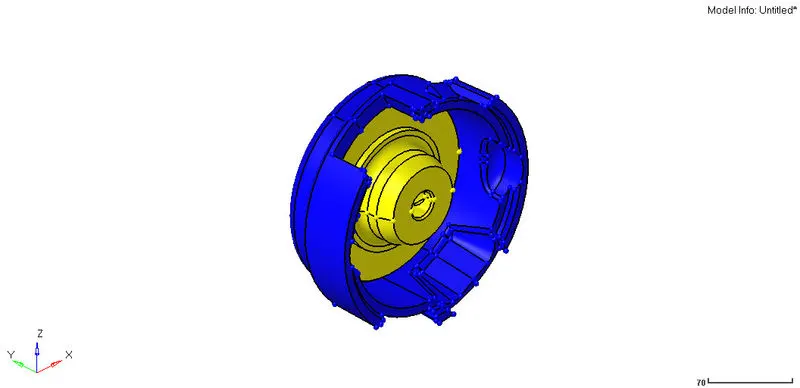
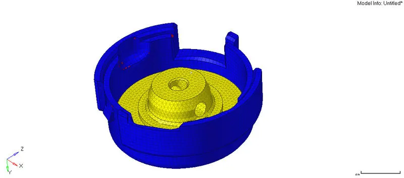
Housing geometry is consist of two different parts, hence each is meshed individually. Following are the procedures for tetra mesh execution.
- CAD model is imported, cleanup is done followed by mesh execution.
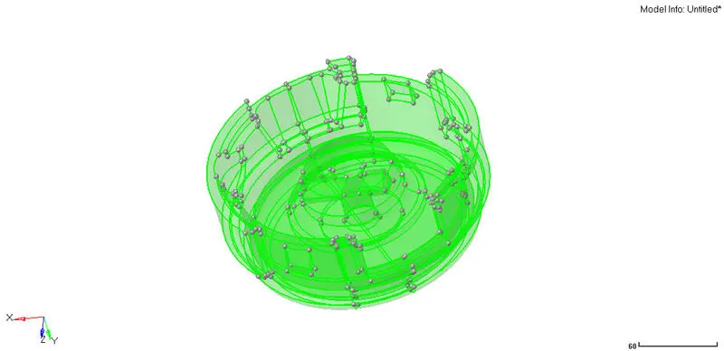
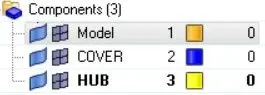
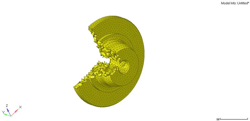
- Firstly, hub component is taken into consideration and 2D mesh is deployed then followed by tetra mesh.
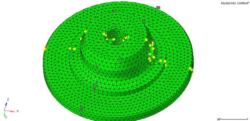
- Tetra mesh command is used to generate 3d elements along with elemental size of 5mm

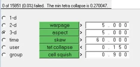
- Quality parameter such as tet collapse can be check here,
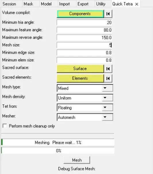
- now. the cover part meshed using quick tetra mesh in utility option.
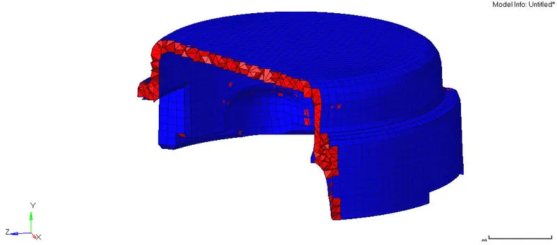
- In such way, The Tetra mesh execution is done.
- ARM BRACKET MESHING - HEXA MESHING
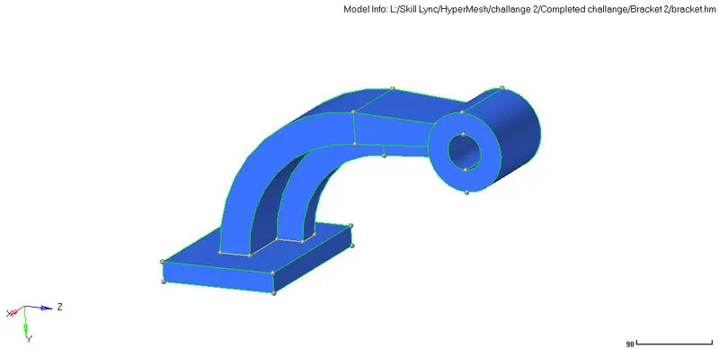
Procedures for hexa meshing are as follows,
- Once the model is imported , geometric cleanup is done.
- Base plane is first 2d meshed with an elemental size of 10 mm
- The generated 2d mesh elements are first converted in 3d along the surface of the base. Here, the element type used is quads.
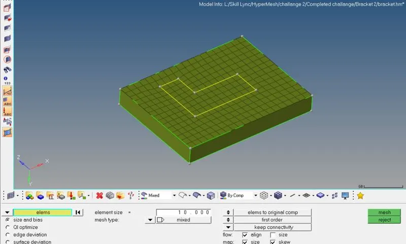
- Now the 2d meshed is converted into 3d along the surface of the base component and its generated 3d elements are stored in it. Using element offset, the 2d base elements are selected and are offset along the surface of the base for a total number of 5 layers and total thickness of 25mm.

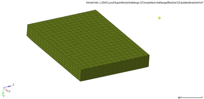
- Now, the curve arm is switch on, here we are suppose to spin the base plate's element along the arm at an angle of 90 degree. To do so, we select the spin element option in 3d followed by the element selection and the base point with normal axis. angle is specify as 90 degree with on spin as 25.
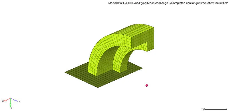
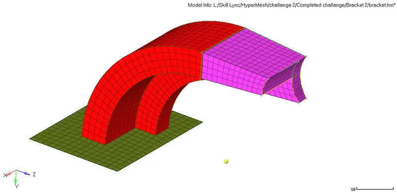
- The arm straight component is also meshed using linear solid. The faces of curved arm is selection along with the straight arm's destination mesh surface and the solid is generated.
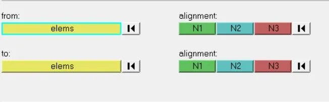
- similarly, the boss or cylinder compont, whose base is firstly meshed, followed by the solid mapping, where the base elements are mapped along the entire components.
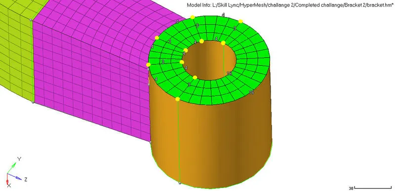
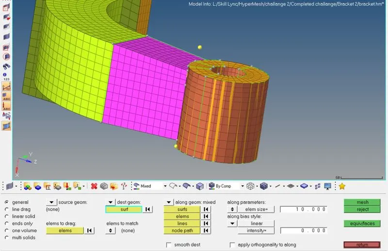
- finally, the entire Arm Bracket is meshed.
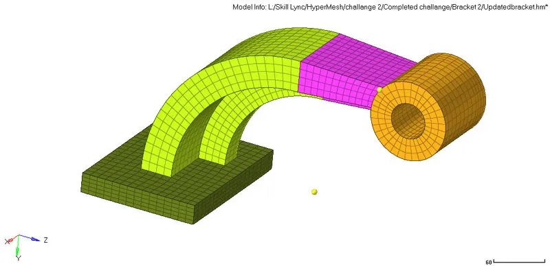
RESULT: In this way, both tetra & Hexa mesh id deployed over the component.
CONCLUSION:
- Any base component can be 2d mesh and it can transfer as 3d solid along the entire component.
- Generated elements can be later stored inside its organised components.
- elements can be spin along an anle, they can be also solid map, linear solid.