3D Creation of Celing, Roof, Architectural plan, Structural plan, Sectional view, Elevation view and Camera specific view for a house plan using REVIT
Q1) Based on the project saved from Week 3, proceed from the First Floor Level. Model a Ceiling from the architecture tab above the walls at the first-floor level
Ans:
AIM: TO CREATE CELLING FROM THE ARCHITECTURE TAB ABOVE THE WALL ST FIRST-FLOOR LEVEL.
INTRODUCTION: - Create ceilings in a ceiling plan view Ceilings are level-based elements: you create them at a specified distance above the level in which they reside. You can create a ceiling defined by walls, or sketch its boundary. If ceiling includes a grid, the grid is centered in the room.
PROCEDURE:
1. Open a ceiling plan view.
2 Click Architecture tab» Build panel » (Ceiling).
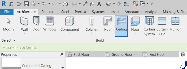
3. In the Type Selector, select a ceiling type.
4. Place a ceiling by usind skecth line boundary method.
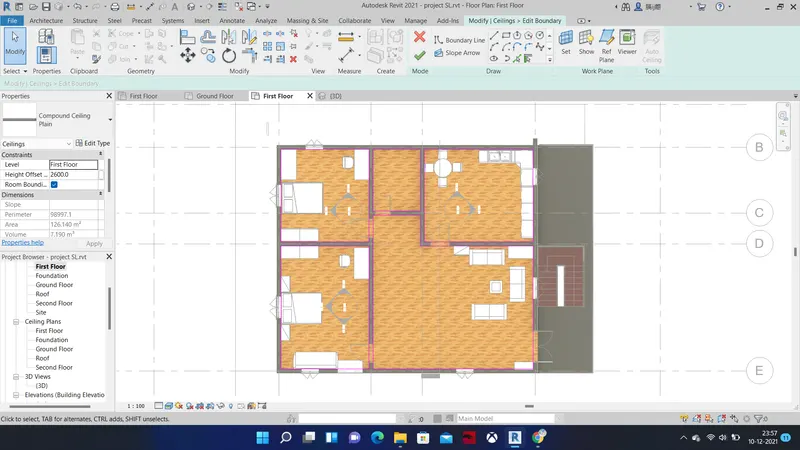
RESULT:
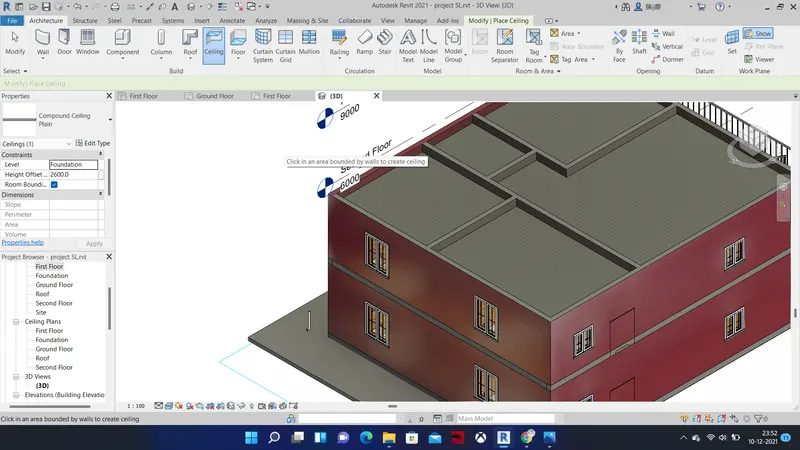
Q2) Model a roof above the ceiling by selecting the footprints of the ceiling. Using the adjustment toolbars appearing on-screen adjust the roof slope to 10 degrees
ANS:
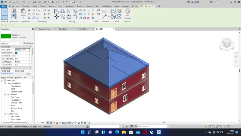
AIM: TO CREATE A ROOF ABOVE CELLING AND ADJUST THE SLOPE OF ROOF.
INTRODUCTION:
Roof is a protective covering that covers or forms the top of a building. Various types of roofs can be made in Revit Architecture.
Roofs can be made from the building footprint, as extrusions, or from mass instances. A roof cannot cut through windows or doors.
PROCEDURE:
Adding Roof by Roof by Footprint
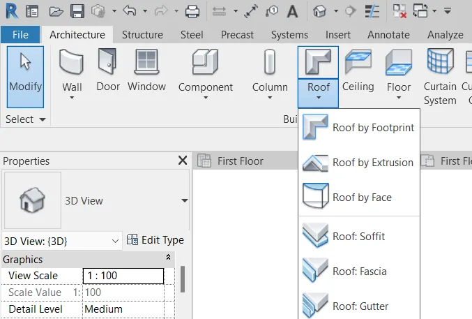
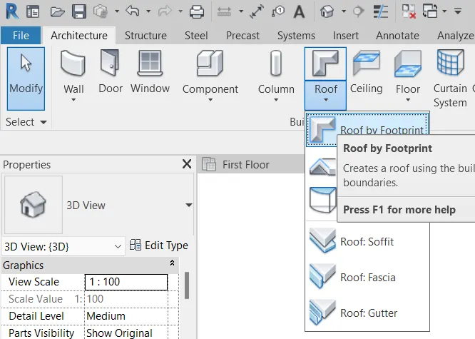
1. 2D closed-loop sketch of the roof perimeter
2. Created when you select walls or draw lines in plan
3. Created at level of view in which it was sketched
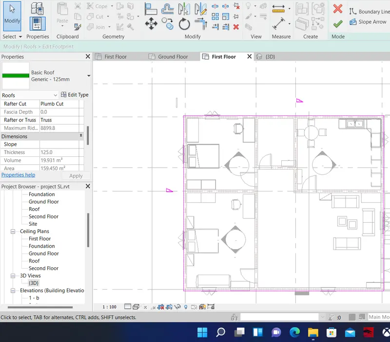
4. Height is controlled by Base Height Offset property Openings are defined by additional closed loops View
5. Slopes are defined when you apply a slope parameter to sketch lines.
RESULT:
Q3) Using the file saved from weeks 2 to 4, create plan views for ground floor level and first-floor level including all the walls, floors, and components. Separate them to
architecture and structural plans
a. Architecture plan must have walls, floors, and all the components placed within the building
b. Structure plan must have details of only walls, floors, and columns
ANS:
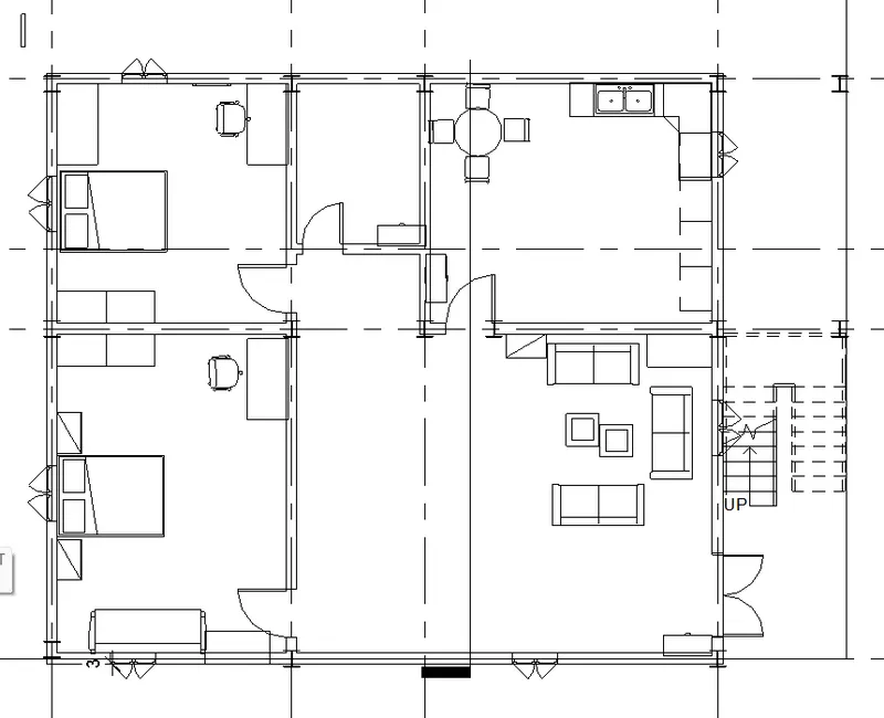
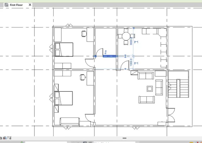
AIM: TO CREATE ARCHITECTURE PLAN AND STRUCTURAL PLAN OF GROUND FLOOR AND FIRST FLOOR.
PROCEDURE:
STEP-1: Lets draw the architecture plan of ground floor and first floor respectively.
step-2: Now, draw the strurtural plan of ground floor and first floor respectively.
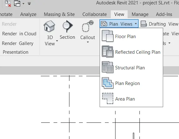
1. go to view menu, click on plan view, from the drop dowm menu select structure plan
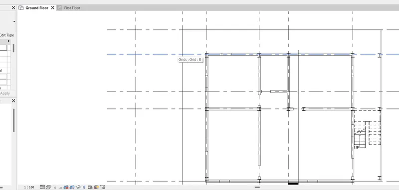
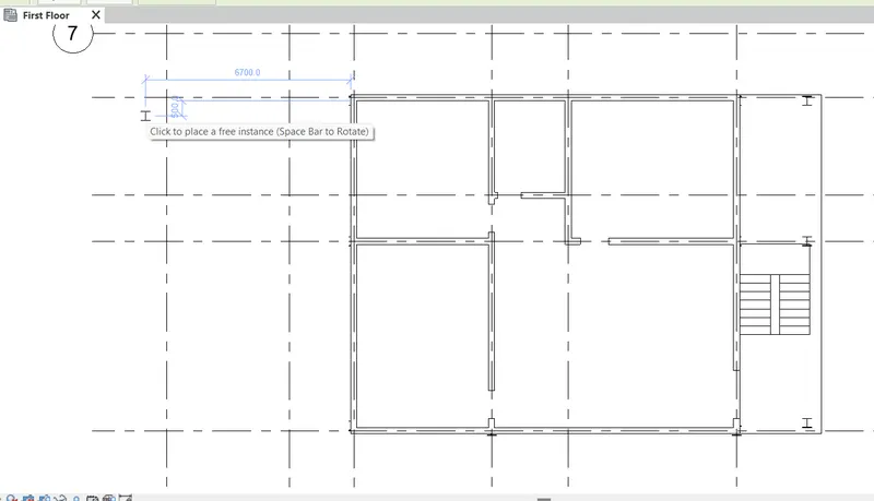
RESULT:
- Created plan view including wall, floor and all the components of ground level and first floor level.
- created architecture plan and structural plan seperatedly.
Q4) Using annotate toolbar add dimensions to all the walls and floors with reference to the longitudinal and transverse grids created in the project file
a. The architecture plan dimensions include details on where the components are placed within the buildings with relation to grids. Overall dimensions are sufficient for architecture plans
b. The Structure plan dimensions must include details on the position of all the walls and interior walls with reference to grids. Locate all the framing components of the building with reference to a fixed point using Structural plans
ANS:
AIM: To add dimensions to all the walls and floors with reference to the longitudinal and transverse grids created in the project file.
INTRODUCTION:
Dimensions are view-specific elements that show sizes and distances in a project. There are 2 types of dimensions: temporary and permanent.
Revit places temporary dimensions as you place components. You create permanent dimensions to define a particular size or distance. Each dimension type can be modified, and the component that is dimensioned updates accordingly.
PROCEDURE:
1. Click Annotate tab » Dimension panel (Aligned).
{Options are Wall center lines, Wall faces, Center of core, and Faces of core. For example, if you select wall lines, the cursor first snaps to the centerline of a wall when you place it over the wall.}
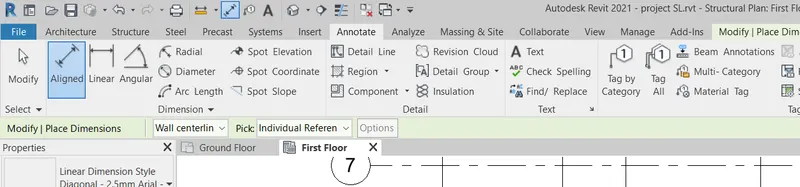
2. On the Options Bar, for Pick, select Individual References.
3. Place the cursor at a reference point on an element, such as a wall. The reference point highlights if you can place the dimension there.
4. Click to specify the reference.
5. Place the cursor on the desired location of the next reference point, and click. As you move the cursor, a dimension line displays. You can continue to select multiple references, if desired.
6. When you have reached the last reference point, move the cursor away from the last component and click.
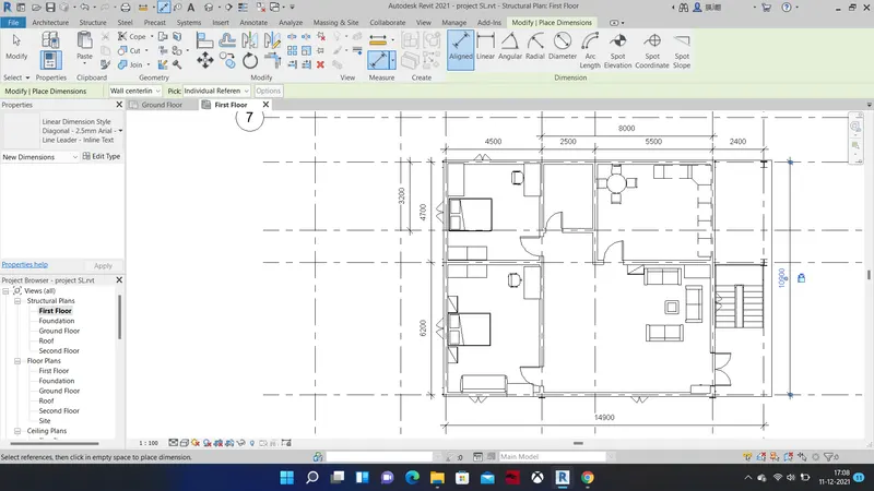
7. The permanent aligned dimension are displayed in below
these below dimenstions are of architecture plan of ground floor and first floor
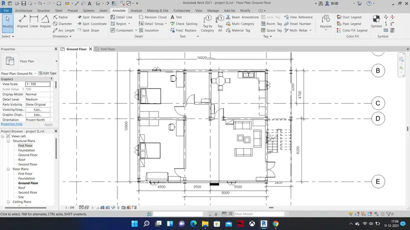
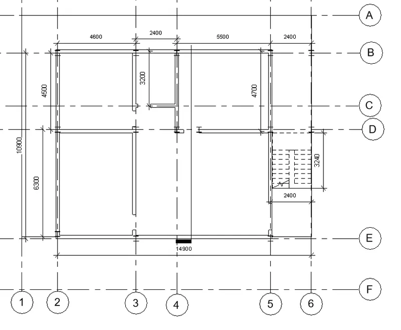
these below dimenstions are of Structural plan of ground floor and first floor
Q5) Create a sheet template from the view tab and adjust the parameters on the sheet to add appropriate views
ANS:
AIM: To Create a sheet template from the view tab and adjust the parameters on the sheet to add appropriate views
PROCEDURE:
STEP:
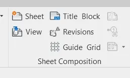
1. firstly go to view tool bar, their we can see the sheet option.
2. after cliking on sheet we can see the new popup on screen as mentioned below.
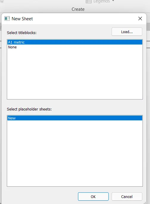
3. in this new tab select A1 Metric and click ok, a sheet gets generated,
4. In this sheet we have to insert the ground floor plan.
5. then edit the project name and sheet number .
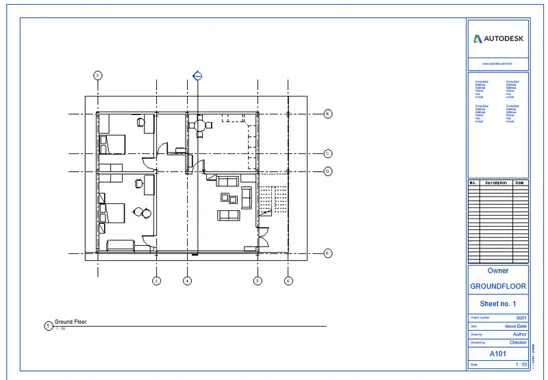
6. repeat the same teps from 1 - 5 for first floor plan sheet.
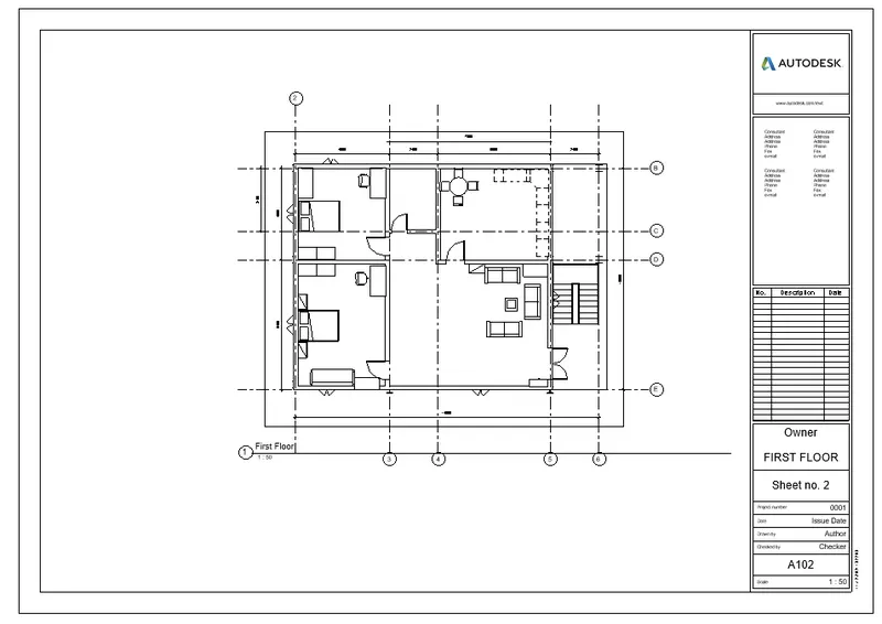
RESULT:
- created the ground floor pla sheet and first floor plan sheet
Q6) Using the elevation tab create the elevation views, looking at your building from East, North, South, and West
ANS:
AIM: To create the elevation views, looking at your building from East, North, South, and West
INTRODUCTION:
Elevation views are part of the default template in Revit. When you create a project with the default template, 4 elevation views are included: north, south, east, and west. It is in elevation views where you sketch level lines.
You can create additional exterior elevation views and interior elevation views. Interior elevation views depict detailed views of interior walls and show how the features of the wall should be built. Examples of rooms that might be shown in an interior elevation are kitchens and bathrooms.
PROCEDURE:
Step:1 go to the view option in toolbar.
2. select the elevation ,
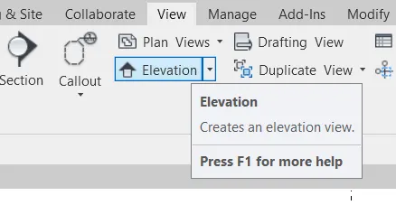
3. select north, the elevation from the north will be visible
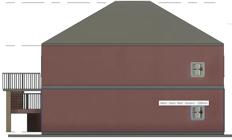
4. select south, the elevation from the north will be visible
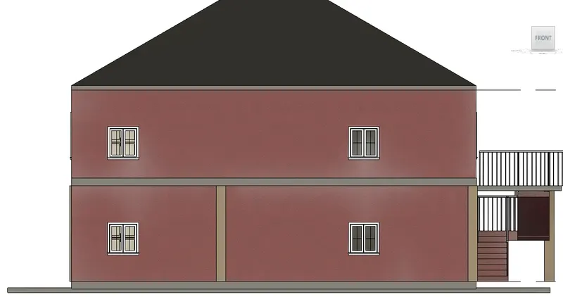
5. select east, the elevation from the north will be visible
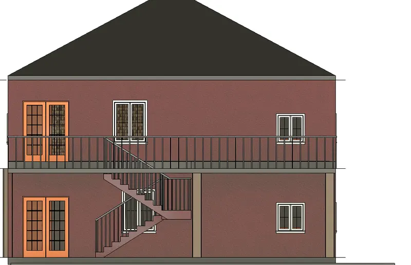
6. select west, the elevation from the north will be visible
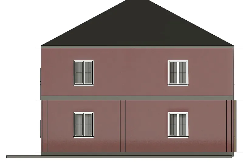
Q7) Produce section cut through each room either cutting across longitudinally or in a transverse direction
ANS:
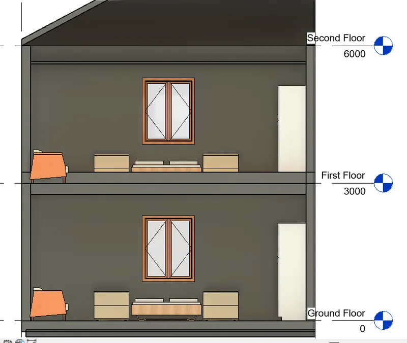
AIM: To Produce Section cut through each room either cutting across longitudinally or in a transverse direction
INTRODUCTION:
- Sectional view shows us the hidden detail inside the structure design
- it is a crosssectional cut throught, representing a cut section of plan.
- these views are mainly used and helpfull for engineering drawing and architectural drawings.
PROCEDURE:
Steps:
1. go to view in toolbar.
2. select section option
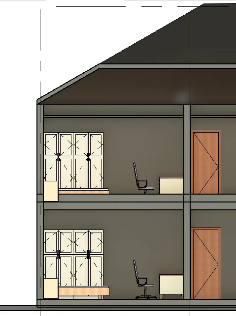
3. using the tool, produce the section view of master bed room
4. using the tool, produce the section view of bed room
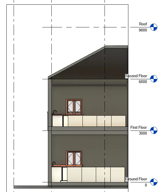
5. using the tool, produce the section view of kitchen room
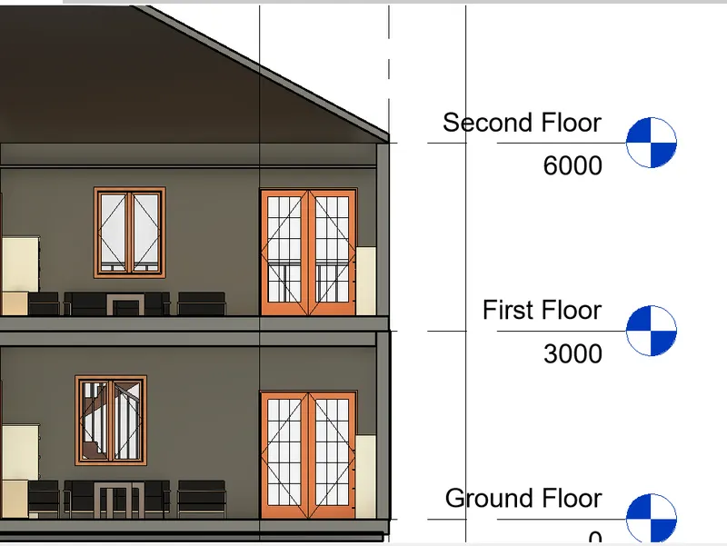
6. using the tool, produce the section view of living room
Q8) Classify the views, Plan Views, Section Views, and Elevation views to either Design or Documentation category using Properties browser
ANS:
AIM: To Classify the views, Plan Views, Section Views, and Elevation views to either Design or Documentation category using Properties browser
PROCEDURE:
STEPS:
1. First open the project browser, we can see view{all} option.
2. expand the view (all) option, shown below.
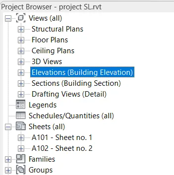
3. Then open a new sheet, insert these plans one-by-one seperatly.
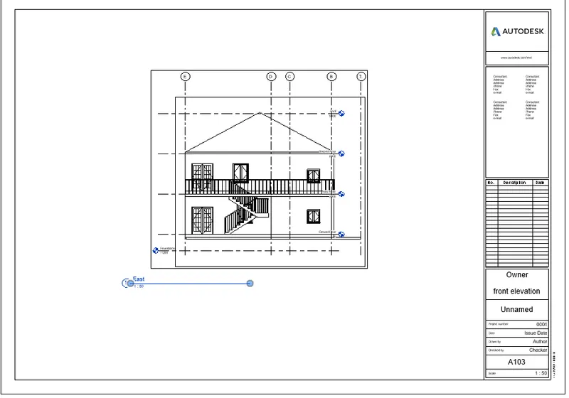
4. inster the front elevation in the sheet template, as shown in fig.
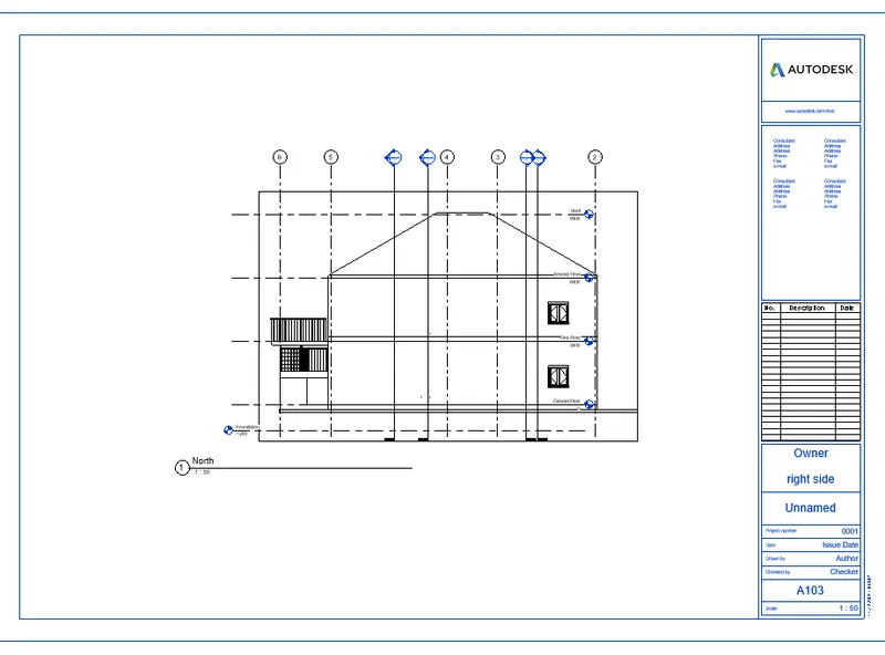
5. inster the right side elevation in the sheet template, as shown in fig.
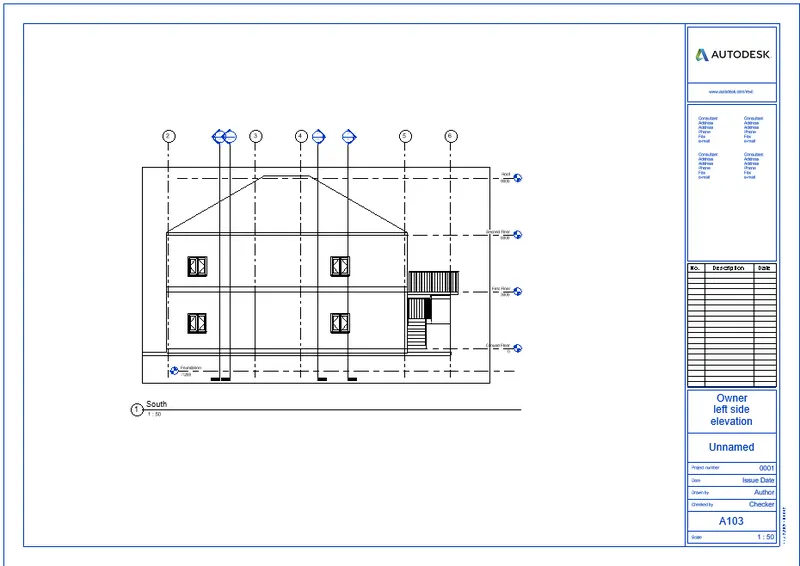
6. inster the left side elevation in the sheet template, as shown in fig.
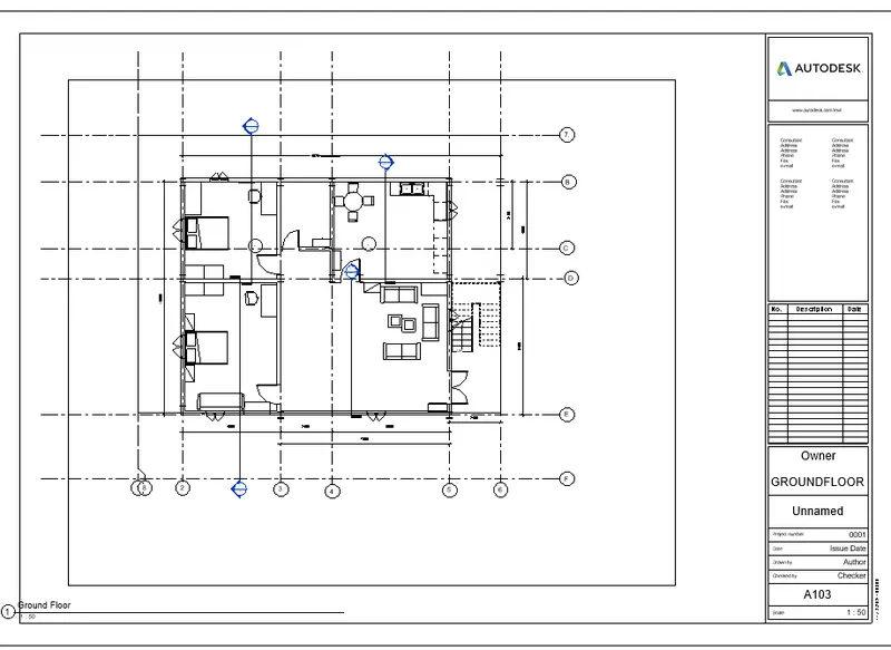
7. inster the ground floor plan view in the sheet template, as shown in fig.
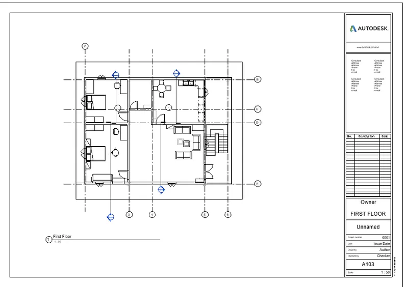
8. inster the first floor plan view in the sheet template, as shown in fig.
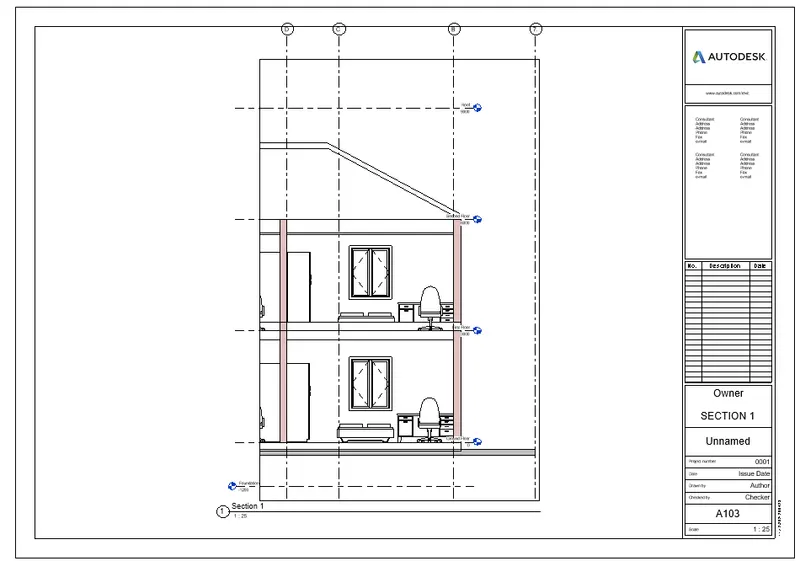
9. inster the section 1 in the sheet template, as shown in fig.
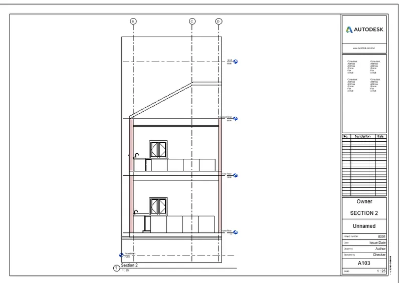
10. inster the section 2 in the sheet template, as shown in fig.
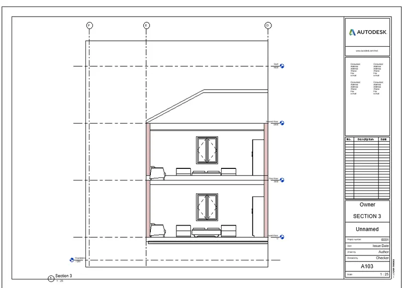
11. inster the section 3 in the sheet template, as shown in fig.
12. inster the section 4 in the sheet template, as shown in fig.
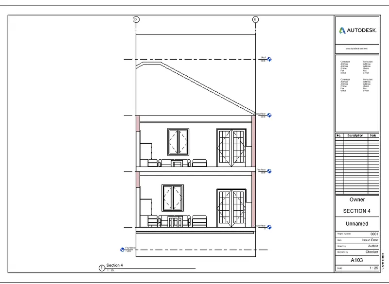
Q9) Using the sheet template produced create multiple sheets as follows
a. A 101- Ground Floor Architecture Plan
b. A 102- First Floor Architecture Plan
c. A 103- Roof Plan
d. S 101- Ground Floor Structural Plan
e. S 102- First Floor Structural Plan
f. S 103- Roof Framing Plan
g. A-201- North-South Elevations
h. A-202- East-West Elevations
Add additional sheets based on the sections created in your Revit file
ANS:
AIM: To create multiple sheets Using the sheet template
PROCEDURE:
step:
1. use the sheet from the 5th que above
2. firstly, provide a architechtural plan sheet of ground floor as, A-101, shown below
3. Then, provide a architechtural plan sheet of first floor as, A-102, shown below
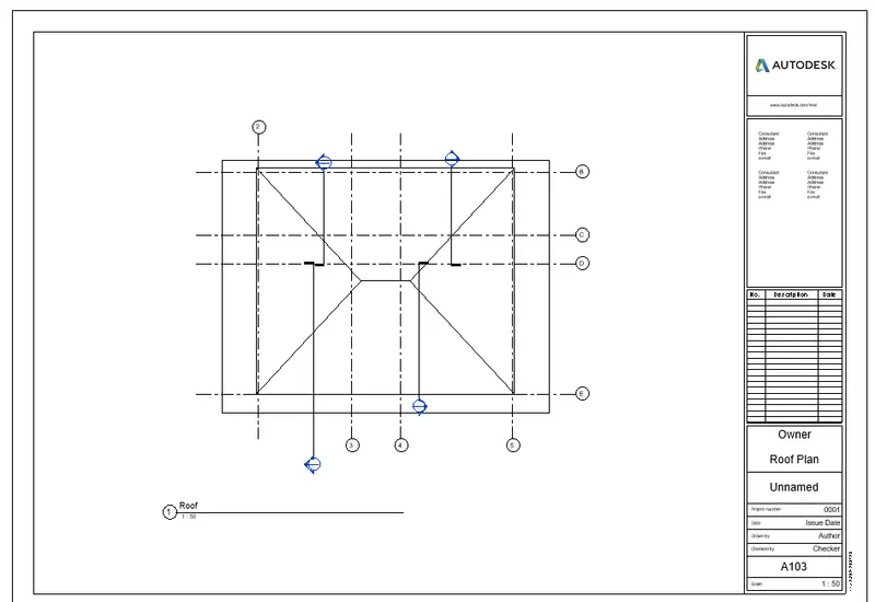
4. next, the roof plan is provided here using sheet template as A-103, shown below
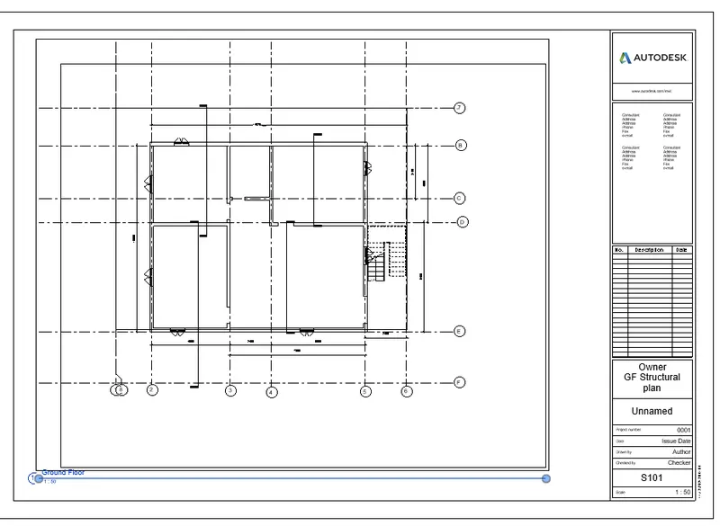
5. then, the ground floor structural plan is provided as, S 101- Ground Floor Structural Plan, shown below
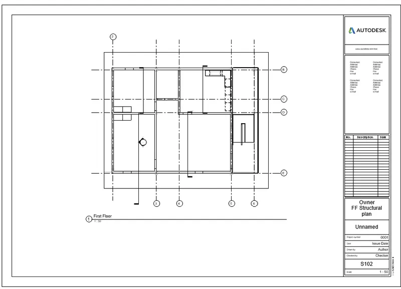
6. then, the first floor structural plan is provided as S 102- First Floor Structural Plan, shown below
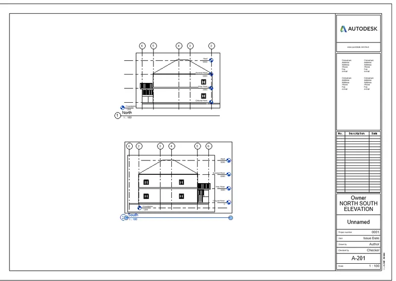
8. then, the North-South Elevations is provided as A-201- North-South Elevations, shown below
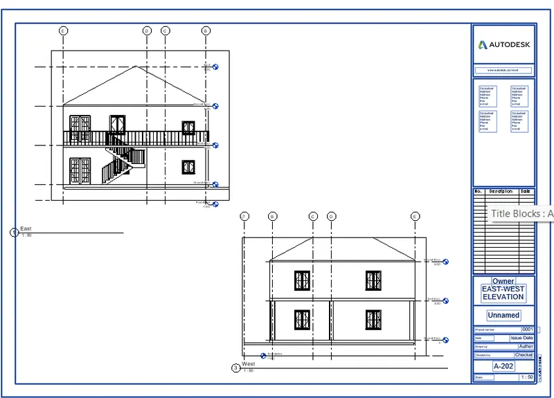
9. then, the East-West Elevations is provided as A-202- East-West Elevations, shown below
RESULT:
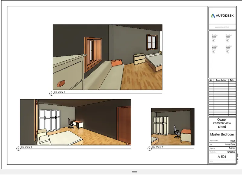
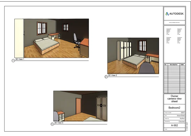
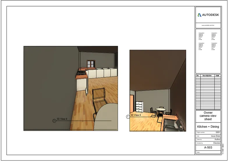
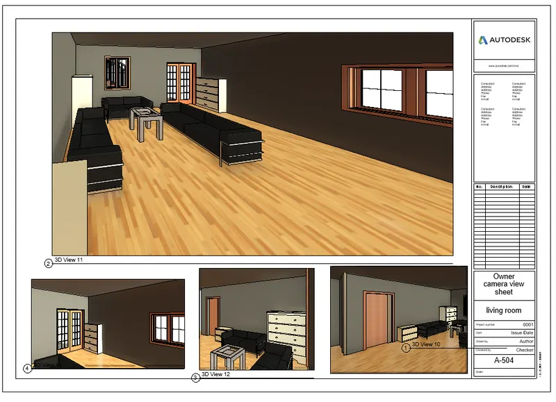
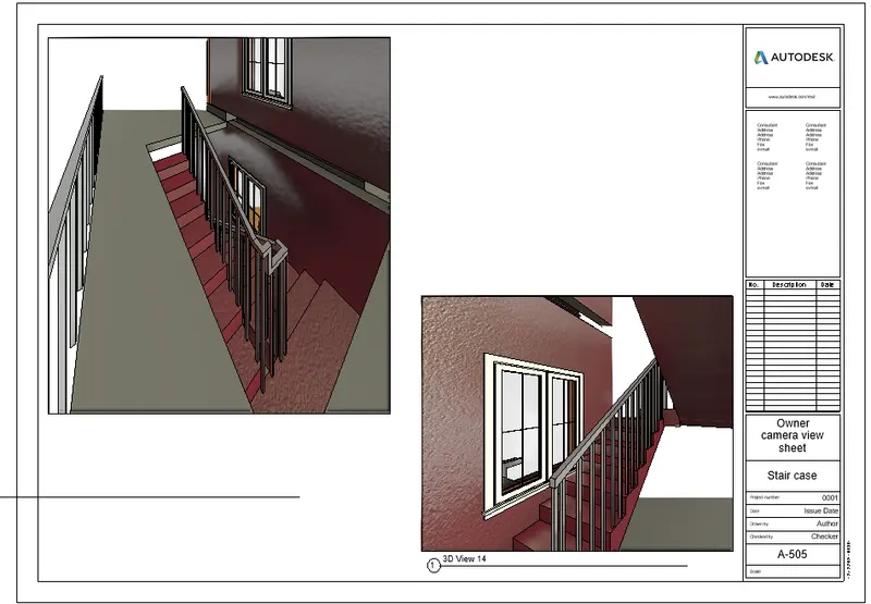
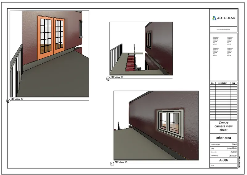
Q10) Create a camera-specific view or a 3D view in each room ( living, dining, bedroom). Based on the views create a new set of sheets starting A-501 (you can add as many sheets after, 502, 503.. n)to place the 3D view images. Produce the sheets as a part of project drafting.
ANS:
AIM: To Create a camera-specific view or a 3D view in each room.
INTRODUCTION:
- Camera views are more likely the view which gives the clear idea of design internally.
- This can be usefull for client and designer to get a clear vision and get in more detail for further steps of construction.
PROCEDURE:
step
1: Go to view in toolbar, then ckick on sheet option.
2: Rename the sheet and spesify the sheet no. starting from A501, ...
3: Then go to the floor plan start placing cameras go get various views as required.
4: Next place the camera view on the sheet.
repeat all the steps for as many views required.
RESULT: