2R Robotic Arm
2R ROBOTIC ARM:
Objective:
The objective of this challenge is to simulate 2 axes degree of freedom robotic arm using forward kinematics.
What is forward kinematics?
Forward kinematics, also often called direct kinematics, are the process of calculating the position and orientation of TCP (Tool center point) given the current values of the joint axes.
Since our robotic arm has parallel axes, it moves about in a plane and hence doesn’t have any orientation to be found also making the problem a 2D rather than 3D. Hence, solving forward kinematics of 2 axes robotic arm (with parallel axes) is quite simpler and can be directly solved using trigonometry.
If the axes were perpendicular solving forward kinematics would be a lot more complex and would need to use Euler angles, Rotation and translation matrices and even Quaternions to some extend to find the location of TCP.
Figure:
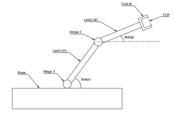
[Note: The length of the links in the figure and the lengths taken in for calculation are not the same hence the figure might look a bit different]
As you can see from the figure there are 2 angles theta1 and theta2 which determine the location of TCP in space. Also, let the lengths of Link1, Link2 and Tool be l1, l2 and t respectively.
For our example let the lengths be:
l1 = 1.2 ft
l2 = 0.75 ft
t = 0 (since we are considering no tool attached)
Let assume the starting point of Link1 (Hinge1) as the origin i.e. x0 = 0, y0 = 0
Let the coordinates of ending point of Link1 (Hinge2) be denoted as (x1, y1)
Let the coordinates of ending point of Link2 (Tool) be denoted as (x2, y2)
Let the coordinates of TCP be (x3, y3)
Calculation:
Step 1: Calculate the position of Link1
Starting point = (x0, y0) = (0, 0)
Ending Point = (x1, y1) = (l1cos(theta1),l1sin(theta1)) ....... using trigonometry
Step 2: Calculate the position of Link2
Starting point = Ending point of Link1 = (x1, y1)
Ending point = (x2, y2) = (x1 + l2cos(theta2), y1 + l2sin(theta2)) ........ using trigonometry
Step 3: Finding location of TCP
(x3, y3) = (x1 + (l2 + t)cos(theta2), y1 + (l2 + t)sin(theta2)) ........ using trigonometry
Solution Set: [x0, y], [x1, y1], [x2, y2], [x3, y3]
Animation:
To create an animation, we need to capture every plot created in the for loop. To do that we use getframe(gcf) command. The we use command movie() to compile the frames captured by getframe() and play the movie. We then create a folder using VideoWriter() command where we can store the movie. Using writeVideo() command we write the movie onto the created file.
Syntax for getfram(gcf):
F = getframe(gcf) captures the current axes as it appears on the screen as a movie frame. F is a structure containing the image data. getframe captures the axes at the same size that it appears on the screen. It does not capture tick labels or other content outside the axes outline.
Syntax for movie():
movie(M) plays the movie in matrix M once, using the current axes as the default target. If you want to play the movie in the figure instead of the axes, specify the figure handle (or gcf) as the first argument: movie(figure_handle,...). M must be an array of movie frames (usually from getframe).
Syntax for VideoWriter():
v = VideoWriter(filename,profile) additionally applies a set of properties tailored to a specific file format (such as 'MPEG-4' or 'Uncompressed AVI').
Syntax for writeVideo():
writeVideo(v,img) writes data from an array to the video file associated with v.
You must call open(v) before calling writeVideo.
Code for solving Forward kinematics in MATLAB:
% Code to simulate a 2R Robotic Arm

clear all
close all
clc

%INPUTS
l1 = 1.2;  %Length of Link1 in ft
l2 = 0.75; %Length of Link2 in ft
t = 0; %Length of Tool in ft
theta1 = linspace(30,90,90); %Range of angular displacement of Link1 in degrees
theta2 = linspace(0,90,90);  %Range of angular displacement of Link2 in degrees

ct = 1;
for i=1:length(theta1)
    THETA1 = theta1(i);
    for j=1:length(theta2)
        THETA2 = theta2(j);

        x0 = 0; %x0 is the X co-ordinate of hinge 1
        y0 = 0; %y0 is the Y co-ordinate of hinge 1

        x1 = l1*cosd(THETA1); %x1 is the X co-ordinate of hinge 2
        y1 = l1*sind(THETA1); %y1 is the Y co-ordinate of hinge 2

        x2 = x1 + l2*cosd(THETA2); %x2 is the X co-ordinate of arm end point
        y2 = y1 + l2*sind(THETA2); %y2 is the Y co-ordinate of arm end point

        x3 = x1 + (t + l2)*cosd(THETA2);
        y3 = y1 + (t + l2)*sind(THETA2);

        %Plotting
        plot([x0 x1],[y0 y1],[x1 x2],[y1 y2],[x2 x3],[y2 y3],'linewidth',3)
        axis([-3 3 0 3])
        pause(0.001)
        M(ct) = getframe(gcf);%Here we capture each frame and save it
        ct = ct+1;
    end
end

%Animation
movie(M) %Using this command we compile all the captured and saved frames into a movie
videofile = VideoWriter('Robotic_arm_video.avi','Uncompressed AVI'); %Here we define the file name and file type of the movie
open(videofile)%Here we open the created file
writeVideo(videofile,M) %Here we write the compiled movie on to the file
close(videofile) %closing the file
Output:
https://drive.google.com/file/d/1Zs7FCtZQLJ_UMJc2mFnr-JWE3OwUXAhJ/view?usp=sharing
To further make this code intuitive we can ask for the input from the user.
For eg:
% Code to simulate a 2R Robotic Arm

clear all
close all
clc

%INPUTS
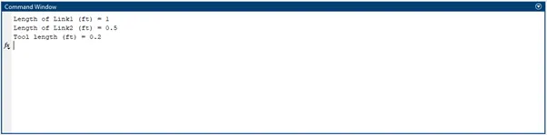
prompt = 'Length of Link1 (ft) = ';
l1 = input(prompt);
prompt = 'Length of Link2 (ft) = ';
l2 = input(prompt);
prompt = 'Tool length (ft) = ';
t = input(prompt);
theta1 = linspace(30,90,90); %Range of angular displacement of Link1 in degrees
theta2 = linspace(0,90,90);  %Range of angular displacement of Link2 in degrees

ct = 1;
for i=1:length(theta1)
    THETA1 = theta1(i);
    for j=1:length(theta2)
        THETA2 = theta2(j);

        x0 = 0; %x0 is the X co-ordinate of hinge 1
        y0 = 0; %y0 is the Y co-ordinate of hinge 1

        x1 = l1*cosd(THETA1); %x1 is the X co-ordinate of hinge 2
        y1 = l1*sind(THETA1); %y1 is the Y co-ordinate of hinge 2

        x2 = x1 + l2*cosd(THETA2); %x2 is the X co-ordinate of arm end point
        y2 = y1 + l2*sind(THETA2); %y2 is the Y co-ordinate of arm end point

        x3 = x1 + (t + l2)*cosd(THETA2);
        y3 = y1 + (t + l2)*sind(THETA2);

        %Plotting
        plot([x0 x1],[y0 y1],[x1 x2],[y1 y2],[x2 x3],[y2 y3],'linewidth',3)
        axis([-3 3 0 3])
        pause(0.001)
        M(ct) = getframe(gcf);%Here we capture each frame and save it
        ct = ct+1;
    end
end

%Animation
movie(M) %Using this command we compile all the captured and saved frames into a movie
videofile = VideoWriter('Robotic_arm_video_input.avi','Uncompressed AVI'); %Here we define the file name and file type of the movie
open(videofile)%Here we open the created file
writeVideo(videofile,M) %Here we write the compiled movie on to the file
close(videofile) %closing the file
Command window:
Output:
https://drive.google.com/file/d/1Zs7FCtZQLJ_UMJc2mFnr-JWE3OwUXAhJ/view?usp=sharing
[Note: In the video you may notice that the length of link2 appears to change size as it moves from 0 deg to 90 deg. That is because of the difference in scale of x axis and y axis]
References:
https://www.mathworks.com/help/matlab/ref/videowriter.writevideo.html
https://www.mathworks.com/help/matlab/ref/videowriter.html