2D Meshing for Sheet Metal
TITLE: 2D Meshing for sheet metal component.
SUMMARY: In this project we have execute 2D meshing of a vehicle's hood. A hood, also referred to as a bonnet is the hinged cover that rests over the engine of a front-engine. Using ANSA software, the geometric hood componet's mid surface has been takeout and subsequently meshed. Various module tools has been used inorder to execute every necessary steps from geometric cleanup, topology to ultimately discretization of the geometry. We removed mostly irregularities that affects the mesh flow to get more refined mesh flow with less percentage of trias elements.
INTRODUCTION: A car's hood is as simple as a sheet metal component. Here, the geometry is taken under consideration in ANSA Graphical user interface. The given geometry itself is a combination of two different components. Hood is again divided in two upper part, lets say metal panel followed by the frame which holds other engine components. The entire Hood geometry can be visualize as below.
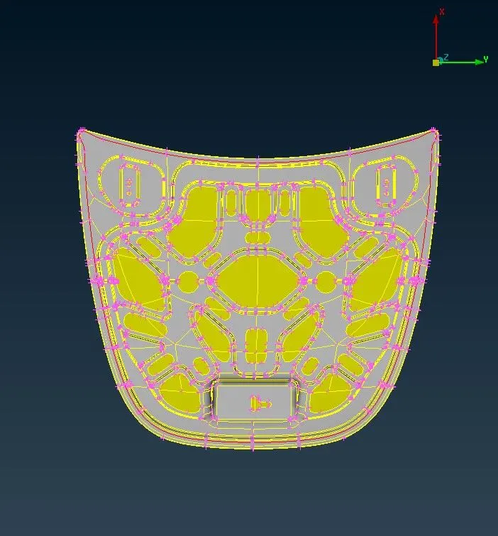
Fig 1.1 Hood Panel (Sheet Metal)
In above geometry, given hood consists of both two different parts they can be also visvualize as below,
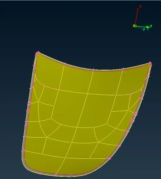
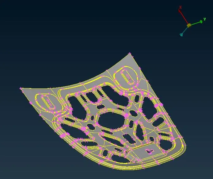
Fig 1.2 (upper part) Fig 1.3 (Middle part)
We have followed various steps in order to execute mesh for given component whose procedures are follows,
- Geometry Cleanup
- Topology
- Midsurfacing of component
- Set PID
- Defeaturing
- Meshing
Procedure:
- The geometry (sheet metal component) hood is open in ANSA user interface. The geometry itself has four different parts, which can be visvualize individually in properties. Each part can be seperately consider for midsurfacing.
- Each parts can be even preciously locked on screen using command as follows, `{``lnot+select surface+middle click+neighbour all+create lock`}`
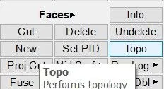
- Now, we perform the topology on geometry in order to join the entire geometric parts with others just in case if they are not. The Topology itself removes any geometric disorders and stiches the parts.
- Geometry cleanup is perform by executing the Checks Manager command from Tool module, followed by geometry check execute command. This command itself gives visibility of found errors in geometry which can be resolve subsequently.
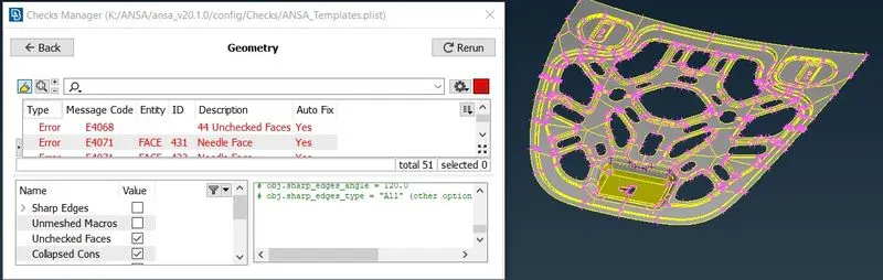 Fig.2.1 Geometry checks manager
- The Check command from Tool module shows a number of triple cons, double cons, crack parts and irregularities in geometry. The executed command also allow to fix certain irregularities automatically however, some of need to be fixed manually using either releasing cons or performing topology.
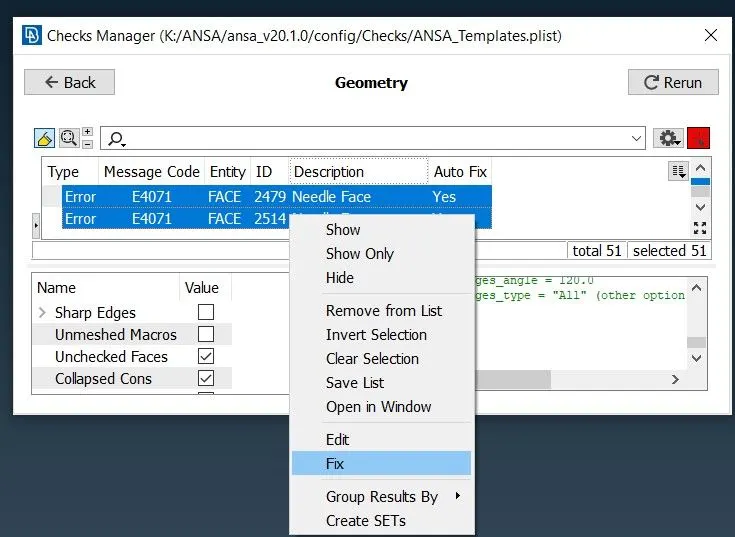 Fig.2.2 Autofix in Checks Manager
- Following are one of those executed procedures which are used to release triple as well double cons, hotpoints and followed by topology.
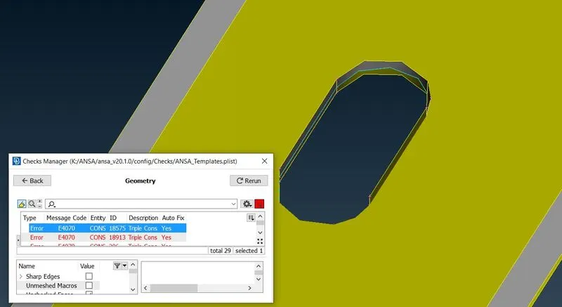
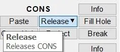 Fig.2.3 Releasing Cons
- We perform midsurfacing of geometry either by using automatic midsurfacing command or by using manual offset method from faces option in module boxes. Same procedure is executed to create midsurface for both parts
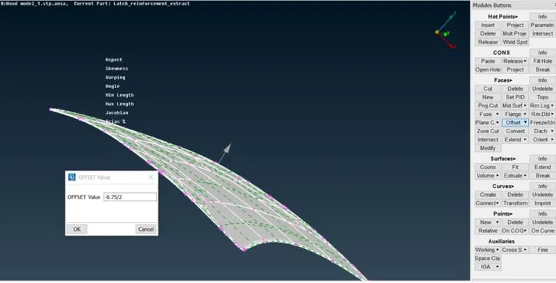 Fig.2.4 Midsurfacing of hood
- Setting up PDI allows us to provide some convenient properties such as thickness, and strutural properties. A PID can only seen in absence of an entity.
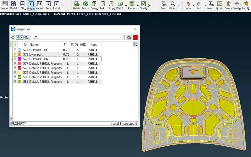 Fig.2.5 Setting up PID
- Once PID is set the geometry is ready for meshing however, there are various pre meshing procedures need to execute in order to get a smooth mesh flow with minimal trias. It is called as Quality criteria. These mostly includes setting up length between each perimeter as 5mm, followed by setting up mesh parameter consisting of max, min and target elemental mesh size, aspect ratios, trias %.
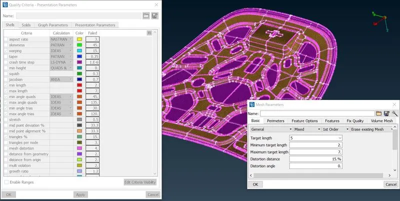 Fig.2.6. Quality Criteria
- Once all quality parameters are updated we can processed with meshing. To get a fine and smooth mesh flow its a best practice to divide geometry in small segments and perform mesh however, we need to perform defeaturing of geometry in order to qualify our quality criteria. Since we have set a targeted values for mesh, if a smaller mesh appears it gonna not pass our quality criteria.
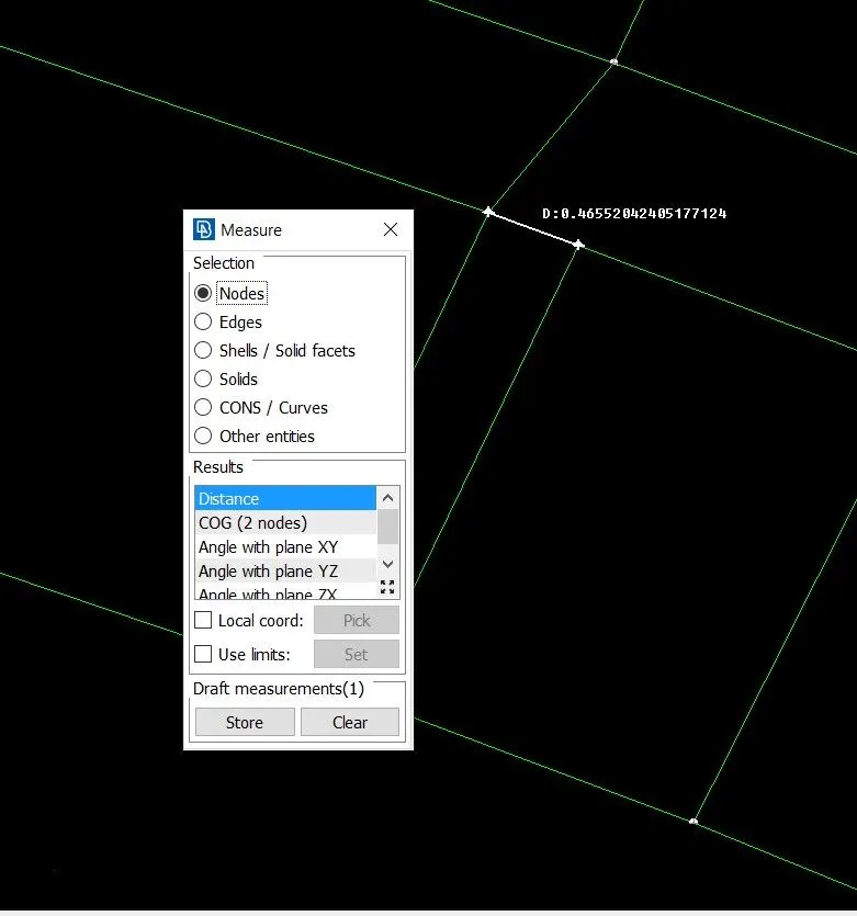
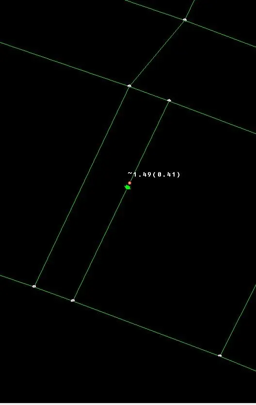 Fig. 2.7 Defeaturing Geometry
- The geometric model must be preserve, we don't need to delete any part since, FE model is dependend on geometry. We defeature by using cut tool from macro module, once they follow the acceptable pattern we perform mesh.
- Execute Mesh Generation tool from Modules on ANSA GUI. We need to use 'BEST' command to mesh. The BEST command itself is the best algorithm for mesh execution. We run the BEST command & select desired part on geometry then click mouse's middle button the mesh is generated.
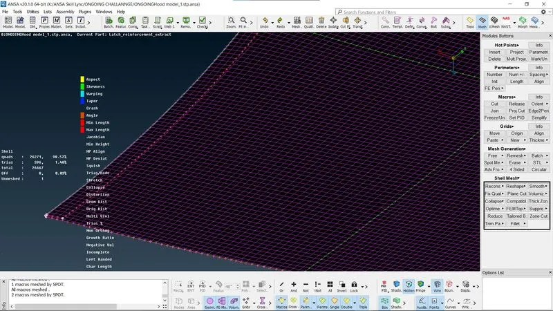 Fig. 2.8 MESH/NET Generation
- For the sake of simplicity & to save time the half geometry can be meshed and copy to its symmetry body. After the mesh is generated there is a possiblity that it contains trias. A tria element will always be in a plane because it takes a minimum of 3 nodes to specify a plane. A quad element can warp if required depending on the applied load. Therefore, Quads are preferred over trias. The trias Elements are eleminated by either using mesh reconstruction command followed by spliting trias or moving them in specific position till they eleminate as shown below.
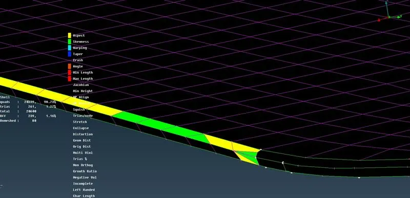
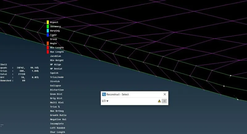 Fig. 2.9 Mesh Reconstruction for fixing trias and abnormalities
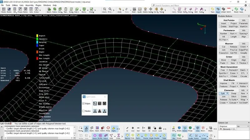 Split Command
- Both parts of Hood components are half meshed and later and copied symetrically.
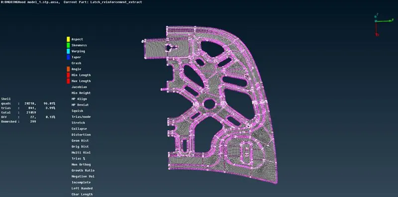 Fig.3.0 Half Mesh (1)
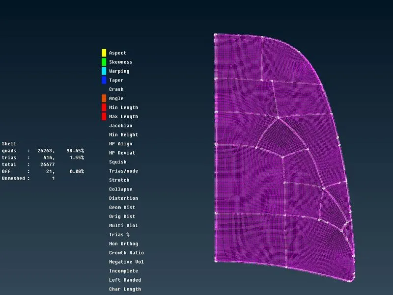
Fig.3.1 Half Mesh (2)
MESHING:
Finite Element Method reduces the degrees of freedom from infinite to finite with the help of discretization or meshing (nodes and elements). One of the purposes of meshing is to actually make the problem solvable using Finite Element. By meshing, you break up the domain into pieces, each piece representing an element. Here, ANSA stands for automatic net genertion for structural analysis. ANSA is used here since, its a powerfull pre pocessor tool.
RESULT:
After performing each procedures with proper understanding, we have sucessfully executed Mesh generation of Hood sheet metal component.
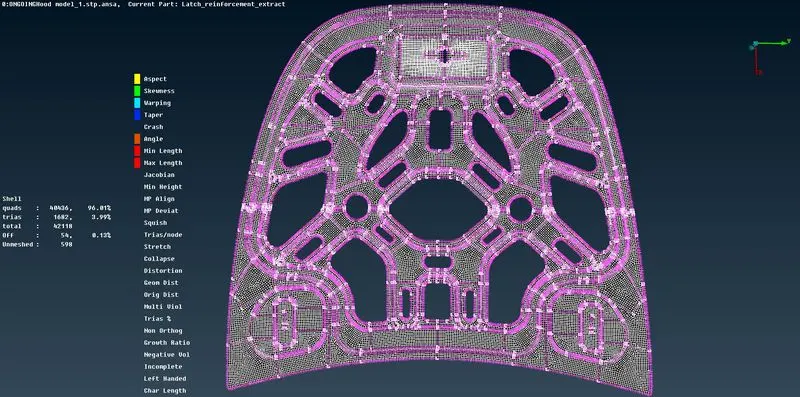
Fig.3.2 Fully Meshed (1)
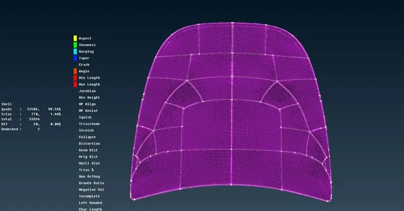
Fig.3.3 Fully Meshed (2)
When combined and viewed both components together we conclude that the hood component is Meshed sucessfully with 97.49% Quad Elements & trias just 2.51%, we have achieved a fine & smooth mesh flow.
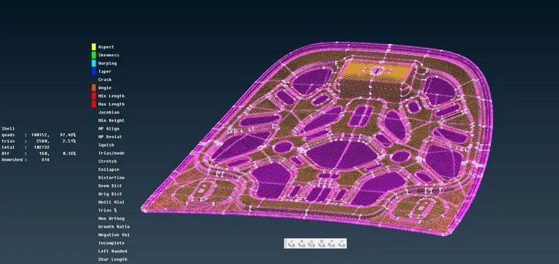 Final Mesh Generation of Hood Sheet Metal Component
LEARNING OUTCOME:
- By performing above mesh execution, one can learn how to remove irregularities like cons, tria elements, geometric errors
- Extraction of Mid surface by manual as well automatic method
- Defeaturing entities
- Importance of Quality criterias
CONCLUSION:
The Hood Sheet Metal component's mid surface is extracted and mesh generation results in refined and smooth mesh flow with trias at 2.1%