2D Meshing for Plastic Components
TITLE: 2D Meshing for a Bottle Cap Plastic Components.
SUMMARY: In this project, we execute 2D Meshing for a Bottle cap Plastic Component. A 3d solid geometry is under consideration, whose mid surface has been exectracted followed by meshing. It consists of various geometric features such as ribs, threads and teeths with varying thickness, whose mid surface exectraction, overcome abnormalities, meshing, post meshing methodology and its procedures are described as follows. Certain Quality parameters along with desired thickness has been assigned.
INTRODUCTION: A bottle cap or bottle top seals the top opening of a bottle. Here, we have consider its solid geometry our aim is to performed various operations which are necessary in order to execute 2d mid surface followed by its meshing. We have also assigned a desired thickness, certain quality parameters and criteria that need to be fulfill. Brief methodology as well as procedures has been described below,
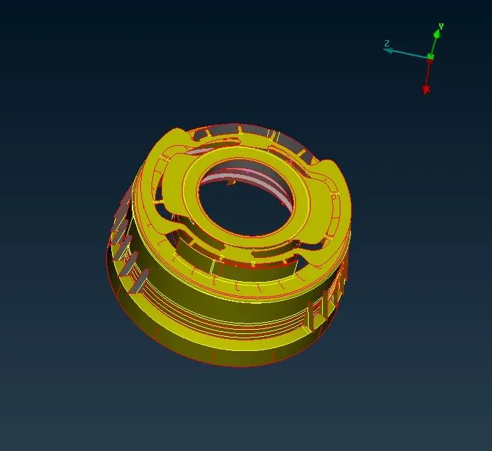 Fig 1.1 Solid Geometry of Bottle Cap
PROCEDURE:
- We open the cap bottle solid geometry in ANSA user interface and perform Topology, now what topology allows us to eliminate certain geometry abnormalities and stiches other surfaces.
- Next we execute a geometry check, under check manager the abnormalities are highlighted such as tripel cons, crack in surfaces and it can be fixed automatically or manually.
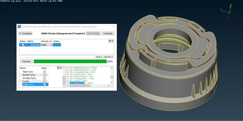 Fig 1.2 Check Manager
- Once the geometry is free of error, we perform mid surface extraction. Any user is suppose to use either manual or automatic mid surface extraction method under faces module. Infact, there are some components in geometry which won't be execute mid surface from mentioned method hence other methodology such as multi midsurface and offset needs to be used.
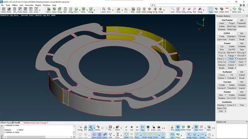
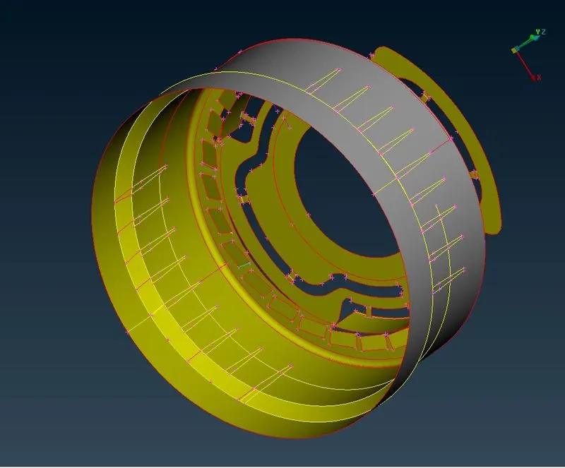
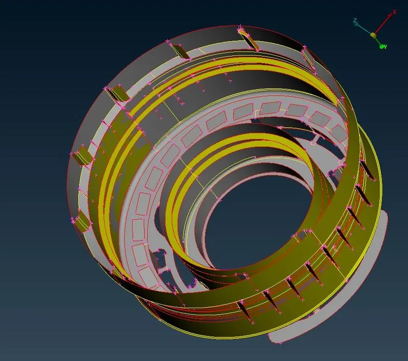 Fig 1.3 Mid Surface Extraction
- The geometry itself consists of various features such as Ribs, Threads and Teeths. Extracting mid surface of these features usually requires different methodology such as using multi mid surfacing, offsets , taking middle curves and projections followed by creating surface out of planes. Following are the mid surfaces taken using above mentioned methodology for features discussed.
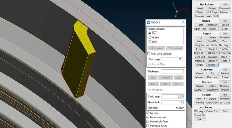 Fig 1.4 Mid surfacing Ribs
- There's various numbers of teeth below the model, whose mid surface has been extractedd using curve middle methodology. The cons has been selected followed by its mid curve generation and projecting the corresponding cons on base mid surface. The cons are then filled using planer face generation. Then the executed teeths are copied on circumference rather than extracting manually each, hence saved a lot of time.
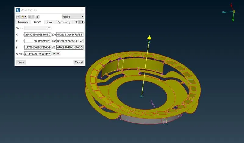 Fig 1.5 Teeth's mid surface extraction
- Similarly, all threads inside the solid model are need to be mid surfaced. Threads seems to be a lot complecated when it comes to extractind its mid surface hence again, we create its mid curve and followed by filling the surface using coons command with base mid surface.
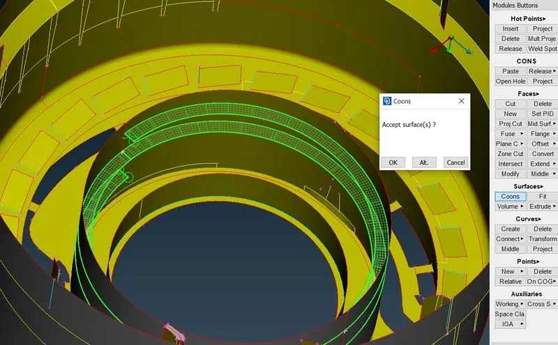 Fig 1.6 Threads Mid Surface Extraction
- Once all methodology is performed we achived overall Mid surface of given solid geometry. There are also certain ribs on the outside of the circumferential of bottle cap. Using manual mid command these are too used to generate mid surface. Fig 1.6 Mid surface of bottle cap
- A new PID is set along with parametric values such as thickness is assigned with a visible color.
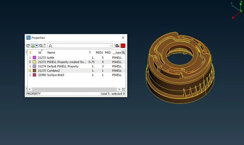 FIG 1.7 PID command
MESHING:
The Elemental size for given componenet is 1mm as per quality parameter. We assigned all given values of quality parameter in order to fulfill creteria.
| Quality Criteria | Values |
| Target/Average length | 1 mm |
| Minimum Length | 0.5mm |
| Maximum Length | 3 mm |
| Aspect | 3 mm |
| Skewness | 45 |
| Jacobian | 0.7 |
| Minimum Quad Angle | 45 |
| Maximum Quad Angle | 135 |
| Trias % | 15 |
Meshing begins with the bottom part of the geometry. Under MESH Module, we execute mesh using BEST command which is far the most appropriate methodology for mesh generation since it used the advance algorithm in it. The Mesh also has been created step by step for getting desired meshflow. The cons or any other lines are cut in order to reach quality criteria or defeatured as per required. The meshed geometry is observed under shadow mode for any abnormalities. The Mesh reconstruction command allows to recreate a mesh if any trias are observed. Trias are also elinimated using split or paste command.
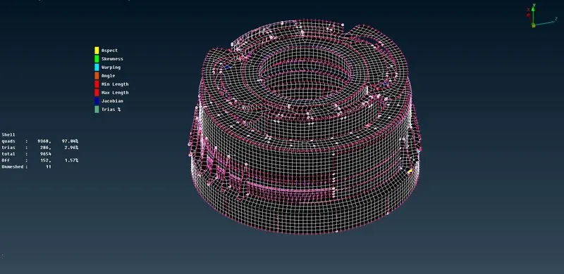 FIG 2.1 Meshed model under shadow mode
From above meshed model under shadow mode, it is clear the we have achived a 97.04% of quads elements along with just 2.96% of trias. There are also no visible error or fail elements which surpasses quality parmeters. The generated mesh can be even reconstructed or smoothened in order to achive top most quality of meshflow with less amount of trais.
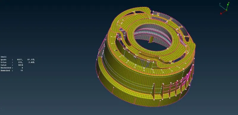 FIG 2.2 Meshed Bottle Cap Model
CONCLUSION:
The bottle cap component has a varying thickness along with various geometric features such as teeths, ribs and threads. At some point the model failed the quality parameter, however we used appropriate methodology to overcome those failures and eliminate abnormalities and achived a proper mesh flow. Ultimately, We have achived a total of 97.17% of quad elements and 2.83% of trias for provided bottle cap solid model with good mesh flow.
Learning Outcome:
- Bottle cap geometry came along with different varying thickness, hence extracting mid surface for each feature required a different approach & we executed it properly.
- At instant, the mesh failed certain quality parameters hence we performed mesh reconstruction, smooth mesh command to achive a proper mesh flow.