Comparison of bending in beams
Abstract: -
In this
project work, the comparison between three different cross-sectioned cantilever
beams is done. The beams have rectangular, I-section, and C-section as their
cross-sections. The comparison is done in terms of stress, displacement, and
strain produced during bending load conditions of 1500 N load. After the
analysis, the best cross-section for bending is suggested.
Objective/Aim-
The comparison
between the three types of beams in terms of stress, displacement, and strain
produced during bending load conditions.
Introduction: -
A beam is a
structural component. It normally resists all the loads applied laterally to
its axis. The only mode by which it can be deflected is Bending. Bending is the
behavior of the element when an external load is applied perpendicular to its axis.
When the beam is fixed with one end and its other end is free then the beam is
known as a cantilever beam. When the load is applied to the face perpendicular
to its axis, the beam experiences bending. The bending of the beam induces
internal stresses, strains, and deflections. The bending also depends upon the
support, cross-section, length, and material. The study of these stresses, strains, and deflections
is used to determine the best possible beam (in terms of support, cross-section,
length, and material).
Problem Statement: -
The task aims to check the performance of different types of beams in bending. The beams are extruded to 400 mm from the faces having dimensions mentioned in figures 1, 3 and 5. A load of 1500 N is applied to the smaller faces of all the beams i.e 40mm face of beam 2 and 45 mm faces of beam 1 and beam 3. The results in terms of Strain, Stress, and Displacement are to be compared and the suggestion of the best of the three is to be given.
Procedure: -
For creating the model in SOLIDWORKS
- To create the 2D sketch of the beams as per the given data;
- To extrude the beams’ 2D sketches as per the given data.
For Analysis
- Select the static study;
- Apply the material to the beams;
- Selection of fixed geometry;
- Apply the load;
- Meshing;
- Run the study;
- Comparison of the results.
Model: -
As per the data provided in the challenge, the model was created on the SOLIDWORKS.
Case 1: Rectangular Beam
The various dimensions of the beam are shown in figure 1 (Given Data). Figure 2 shows the model created using the same data.
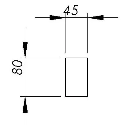
Figure 1. Cross Section of the rectangular beam (Given Data).
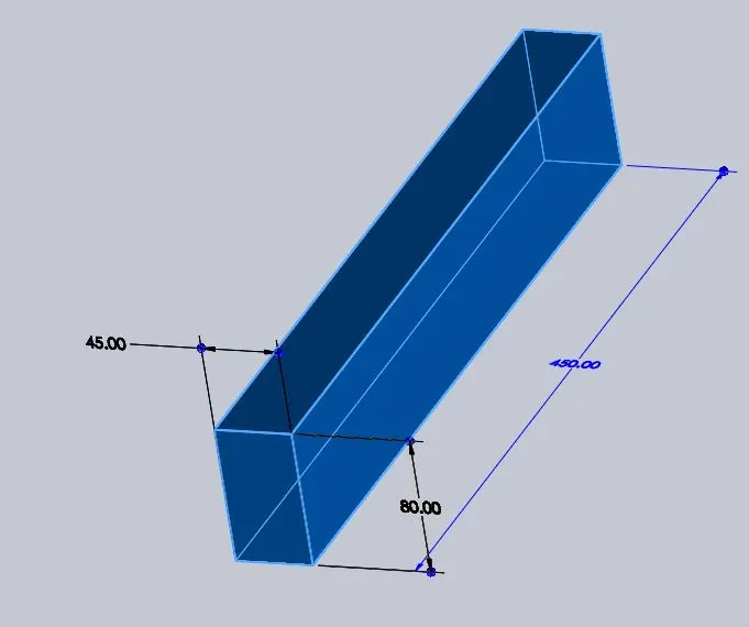
Figure 2. Three-Dimensional model of the rectangular beam
Case 2: I Section Beam
The various dimensions of the beam are shown in figure 3 (Given Data). Figure 4 shows the model created using the same data.
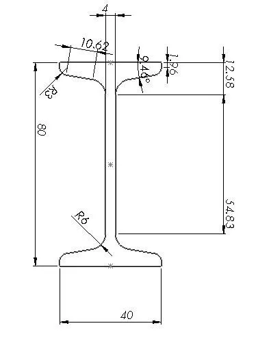
Figure 3. Cross Section of the I - Section beam (Given Data).
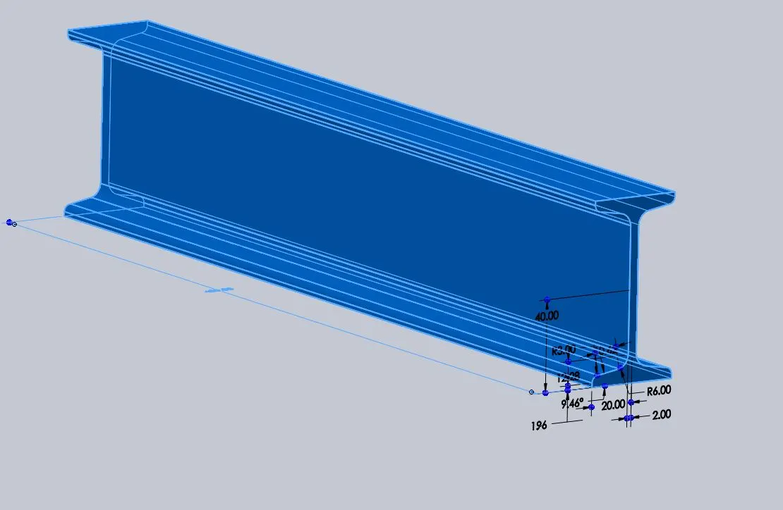
Figure 4. Three Dimensional Model of the I - Section Beam.
Case
3: C-Section Beam
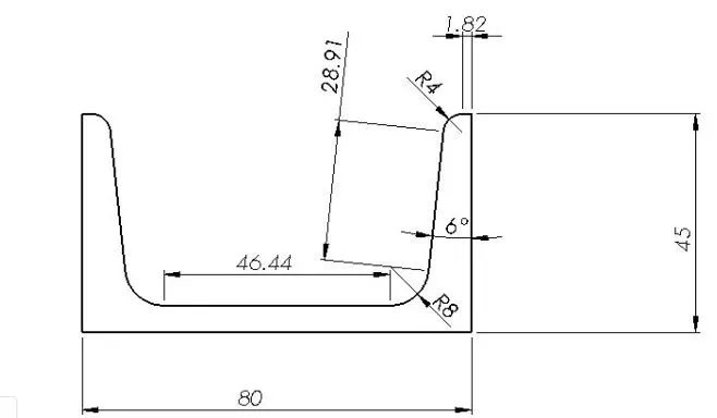
Figure 5. Cross Section of the C - Section beam (Given Data).
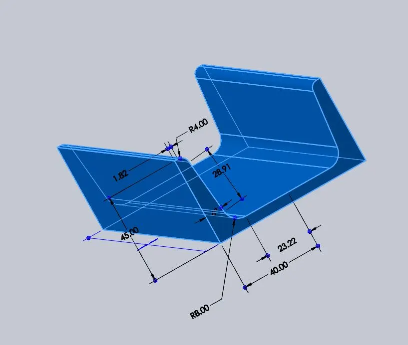
Figure 6.Three Dimensional Model of the C - Section Beam.
Material Selection: -
The material applied to the model was the same for all the
models. The material used for the analysis is the Alloy Steel.
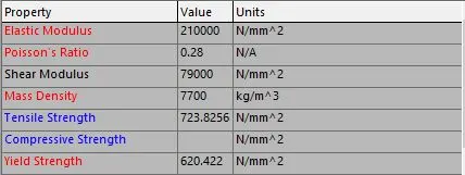
Figure 7. Properties of Alloy Steel
Constraints: -
The model was to be fixed at one end of the beam. This fixture will help the beams to be treated as cantilever beams. The fixture is applied to the face from which the beams are extracted. The fixed geometries are shown for all three types namely Rectangular Beam, I-section Beam, and C-section Beam in Figures 9,8, and 10 respectively.
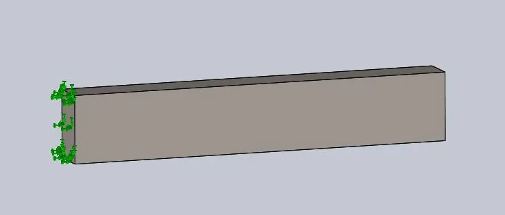
Figure 8.Fixture applied to the rectangular beam.
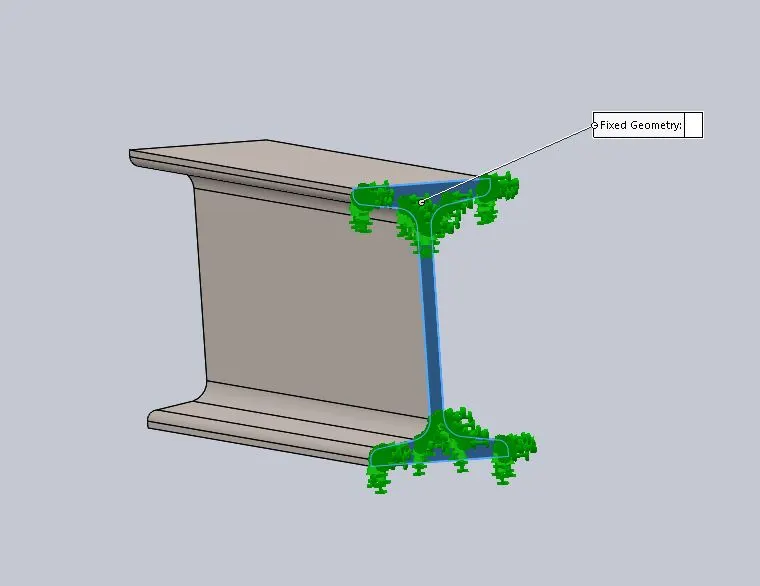
Figure 9.Fixture applied to the I-section beam.
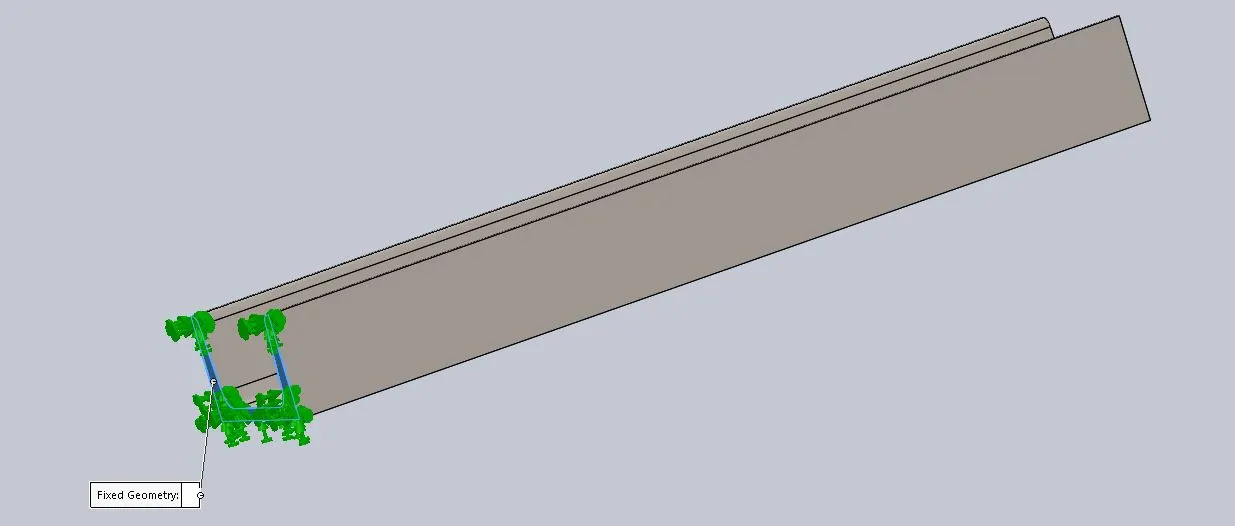
Figure 10.Fixture
applied to the C-section beam.
Application of Bending Load: -
A load of 1500 N was to be applied to the smaller faces of
all the beams.
For case 1, it was on the 45 mm face.
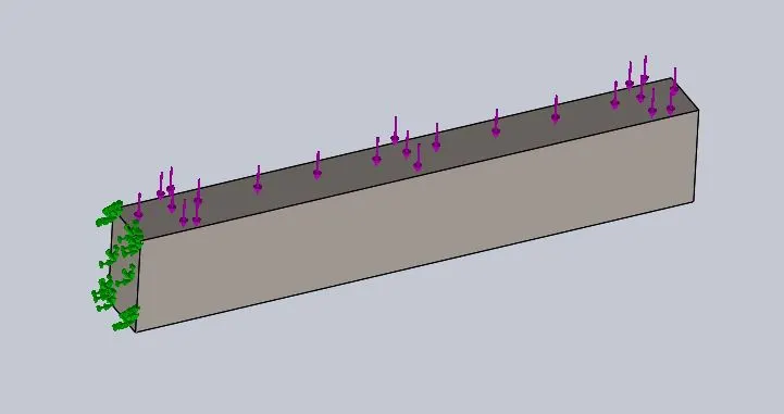
Figure 11. 1500 N load applied on the smaller face (45 mm face).
For case 2, it was on the 40 mm face.
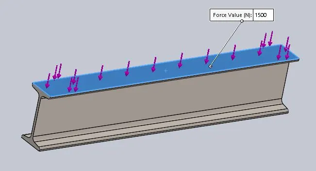
Figure 12 1500 N load applied on the smaller face (40 mm face).
For case 3, it was on the 45 mm face.
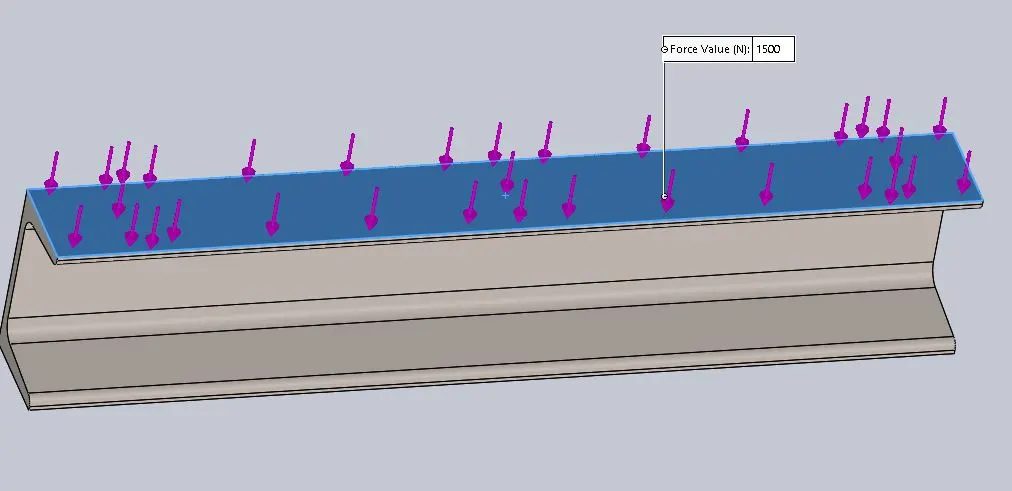
Figure 13. 1500 N load applied on the smaller face(45 mm face).
The load will cause bending and the results are discussed
later on.
Meshing: -
The meshing was done using the following settings for all
the cases:
Size = 5 mm
Tolerance = 0.25 mm
Figures 14,15 and 16 show the mesh.
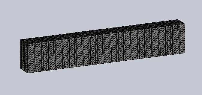
Figure 14. Meshed model of the rectangular beam.
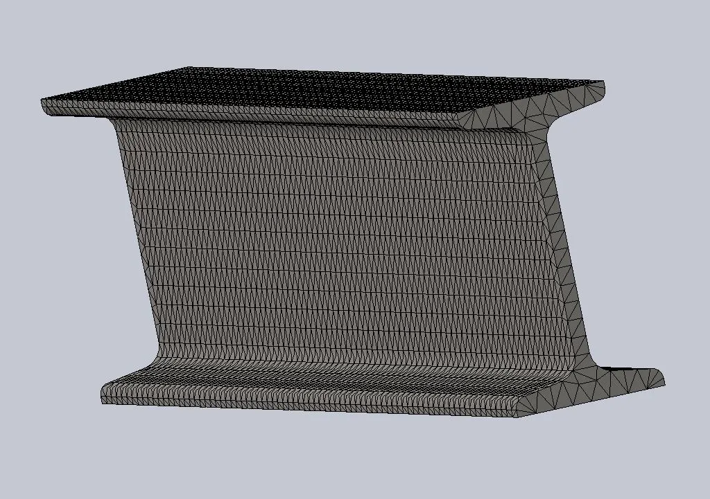
Figure 15. Meshed model of the I-section beam.
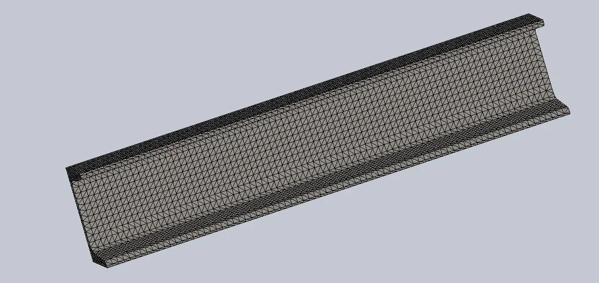
Figure 16. Meshed model of the C-section beam.
Results: -
The results obtained by the analysis are shown below
Case 1: Rectangular Beam
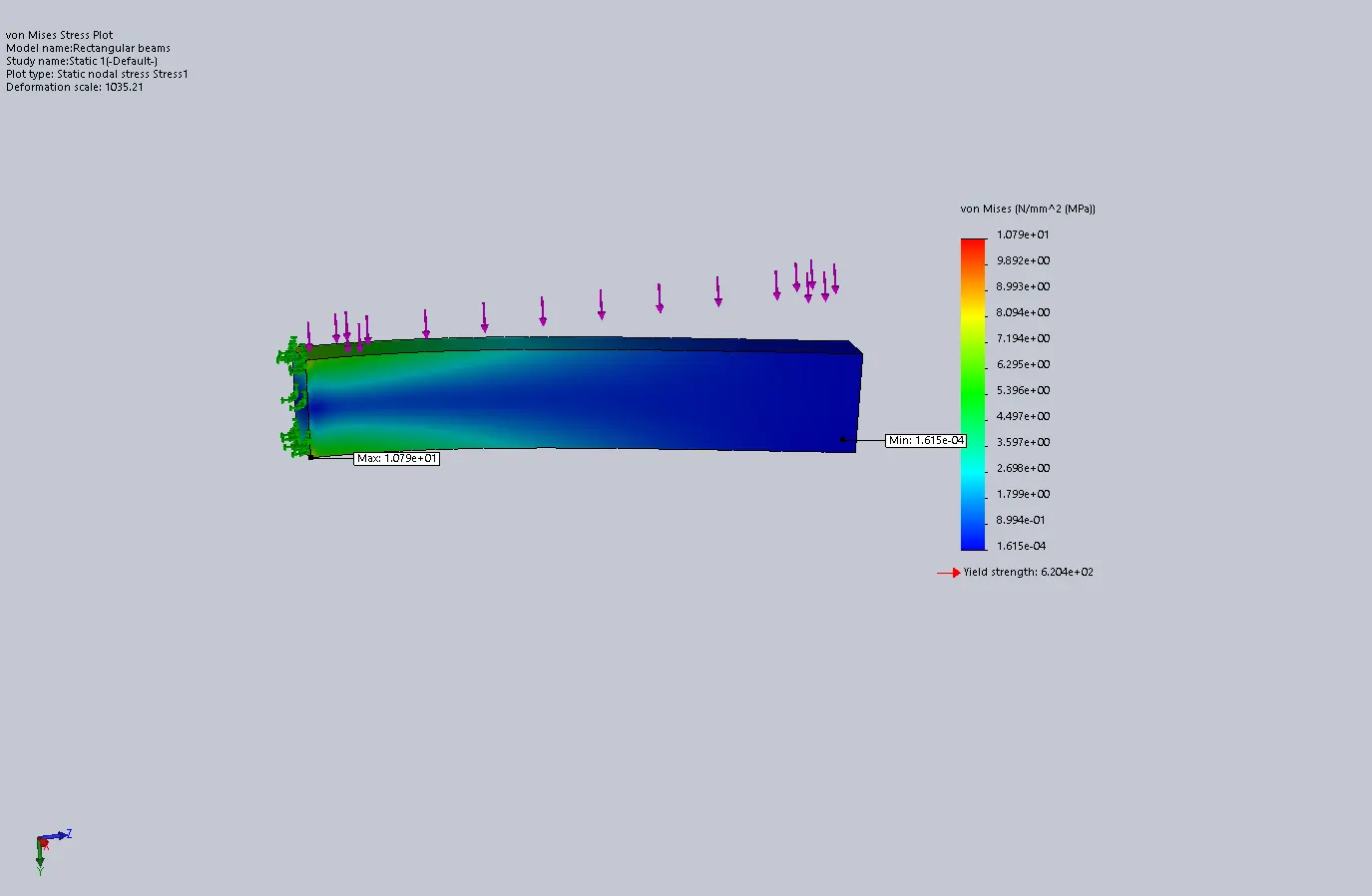
Figure 17. Von misses Stress Plot for the rectangular beam.
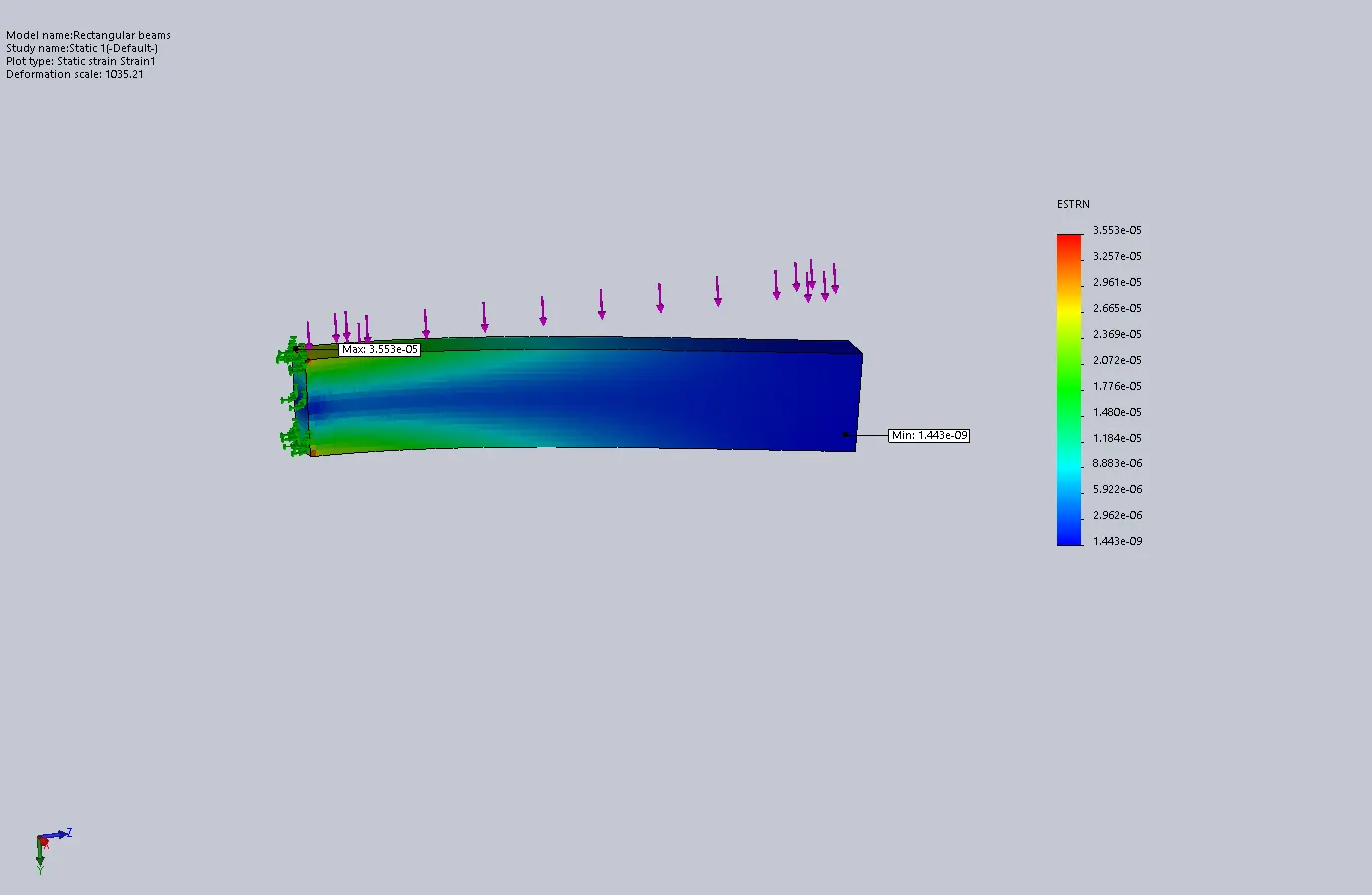
Figure 18. Equivalent Strain Plot for the rectangular beam.
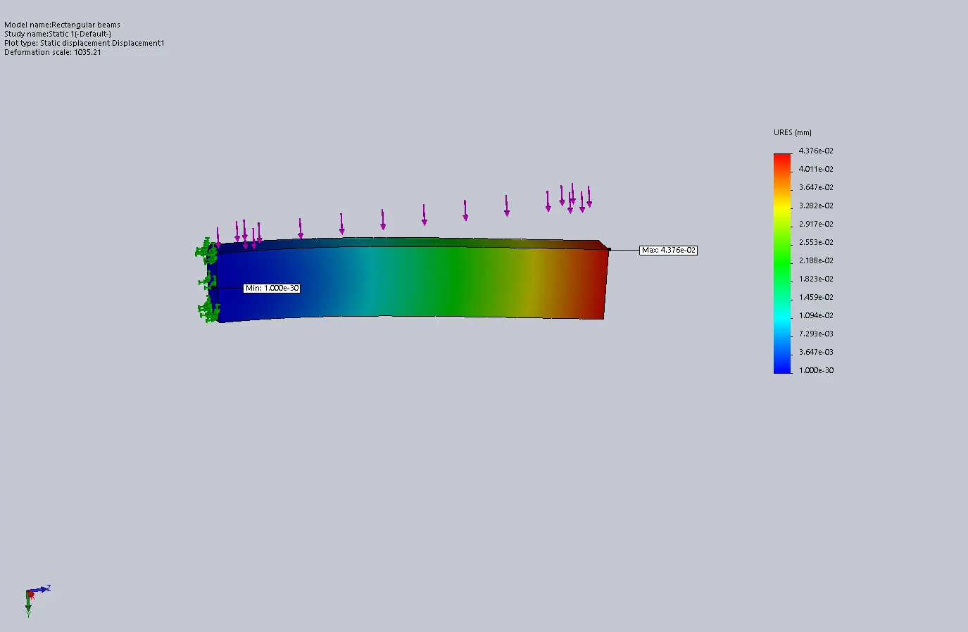
Figure 19. Displacement Plot for the rectangular beam.
Case 2: I – section Beam
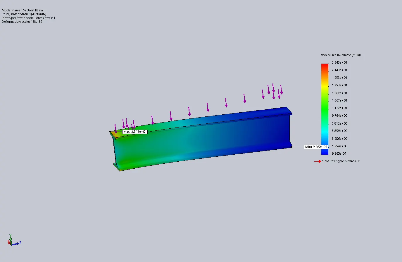
Figure 20. Von misses Stress Plot for the I – section beam.
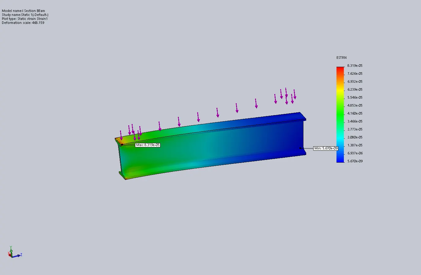
Figure 21.
Equivalent Strain Plot for the I – section beam.
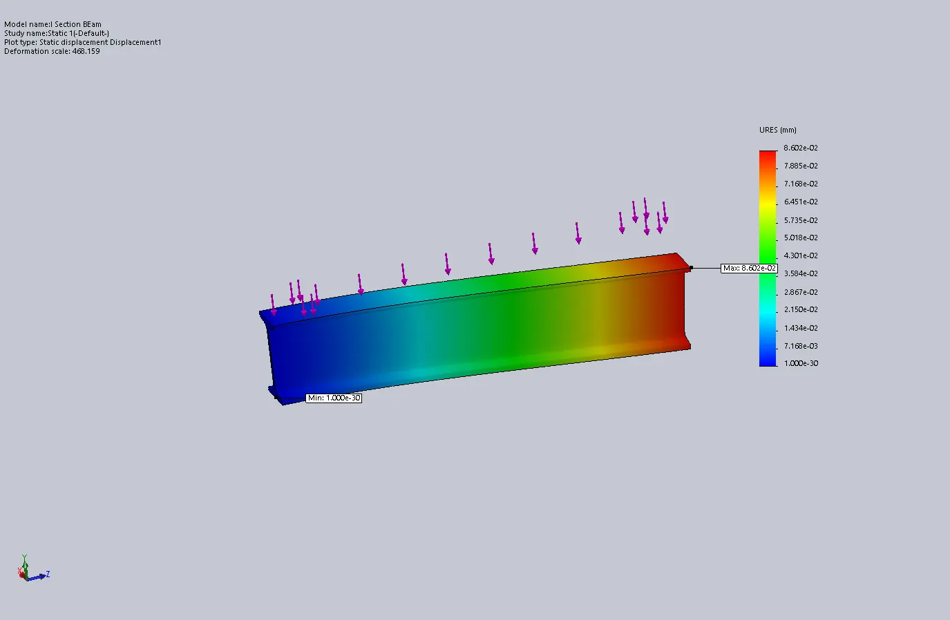
Figure 22. Displacement Plot for the I - section beam.
Case 3: C – section Beam
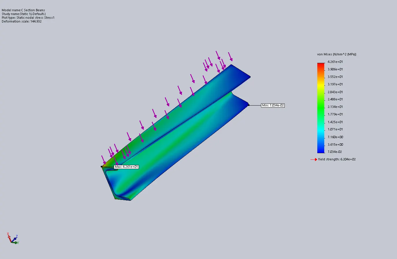
Figure 23. Von misses Stress Plot for the I – section beam.
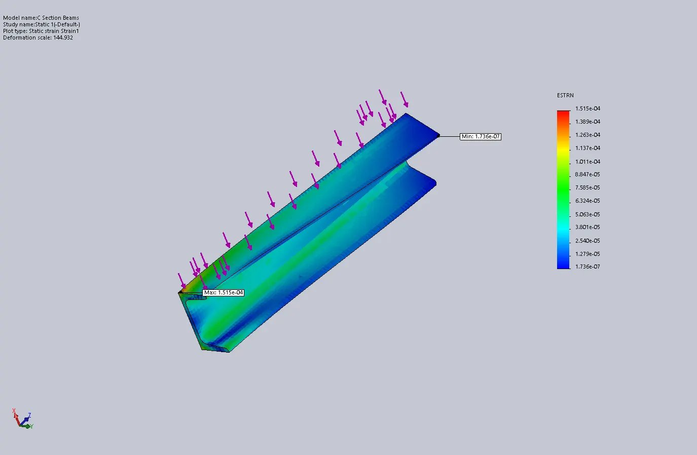
Figure 24. Equivalent Strain Plot for the I – section beam.
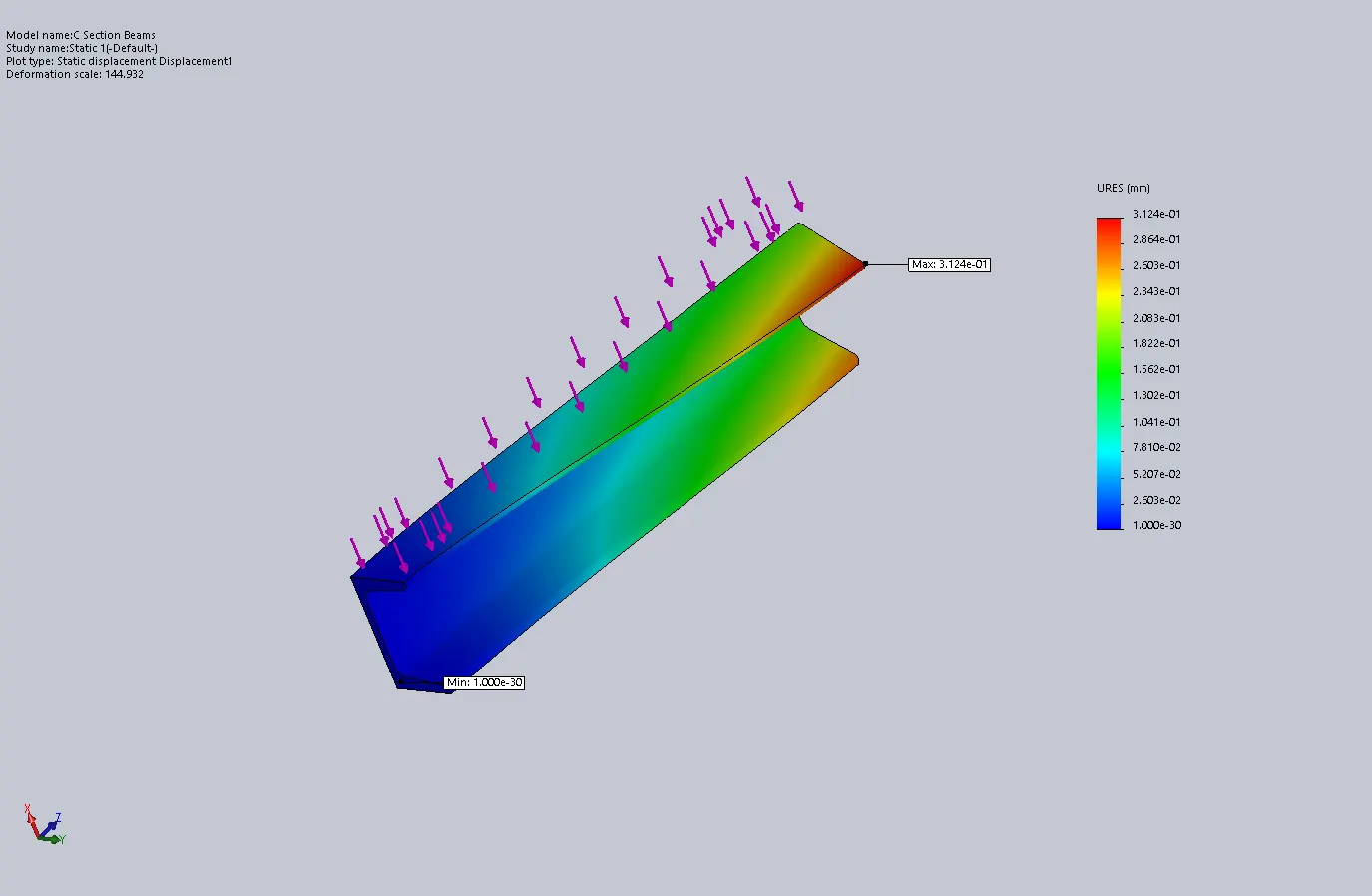
Figure 25. Displacement Plot for the I - section beam.
Comparison of the Results: -
Table1. Summary of results
|
Beam |
Max.
Von misses Stress(MPa) |
Max.
Displacement (mm) |
Max.
Equivalent strain (MPa) |
Factor
of Safety |
|
1 |
10.79 |
0.04376 |
3.553e-05 |
57.49 |
|
2 |
23.43 |
0.08606 |
8.319e-05 |
26.48 |
|
3 |
42.61 |
0.3124 |
1.515e-04 |
14.56 |
As
shown in Table 1, the beam 1 or rectangular beam shows the minimum values in
terms of stress and displacement and also less strain compared to beam 2. The
rectangular beam will be the best choice if we don’t consider the economic and
weight criteria. No one will choose if the material to be used is more and the
cost is high. On the other hand, the C – section beam (beam 3) is the best
option in terms of economy and weight. But, the value of stress and
displacement is high which is not good. Whereas, the I – section beam is good
in terms of stress and displacement as well as equivalent strain. The I –
section beam uses less material, thus reducing weight and cost.
Conclusion: -
As discussed above, the I –
section beam is the best choice among all the beams.