Menu


Modified on
FAQ's In Crashworthiness Analysis

Skill-Lync
Below are the frequently asked questions in Crashworthiness Analysis:
1. Negative volume error
MESSAGE ID: 169
** STOP: ZERO OR NEGATIVE VOLUME
The Negative volume error happens when solid elements get deformed to a very large extent and their characteristic length goes to 0. For large strain formulation, the time step of an element goes to 0 when the element is compressed completely.
Remedy:
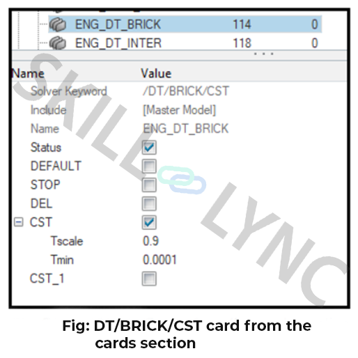
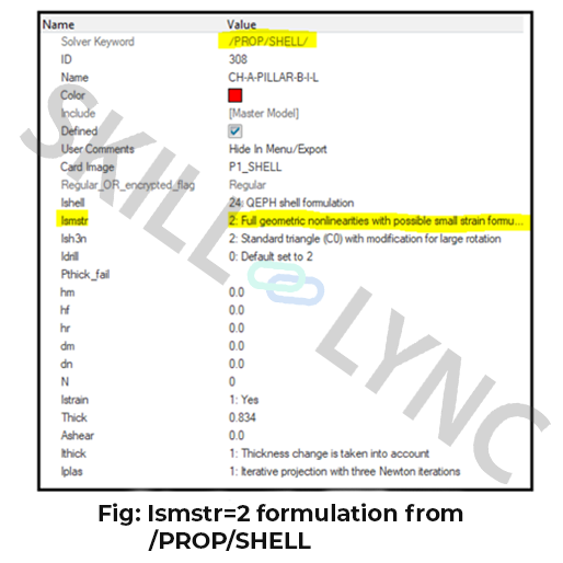
- Use Ismstr=2 in the solid property and use the option /DT/BRICK/CST which will set the time step value tmin at which the solid elements should switch to small strain. This means that when the time step drops below tmin, it automatically switches to a small strain formulation and if it is greater than tmin, it maintains the large strain formulation.
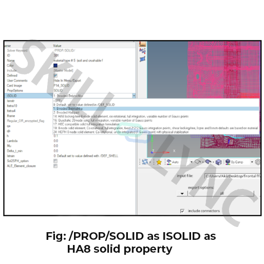
- If the same issue persists even after Ismstr and /DT/BRICK/CST, then use HA8 solid formulation.
- If the solid element is badly warped, that can also lead to negative volume generation.
2. Why are five integration points over thickness preferred?
- One integration point in a shell element leads to the membrane behaviour of that element (a shell element is the combination of plate and membrane elements). They have no bending strength. The reason is bending strength is calculated by integrating the elements over the thickness.
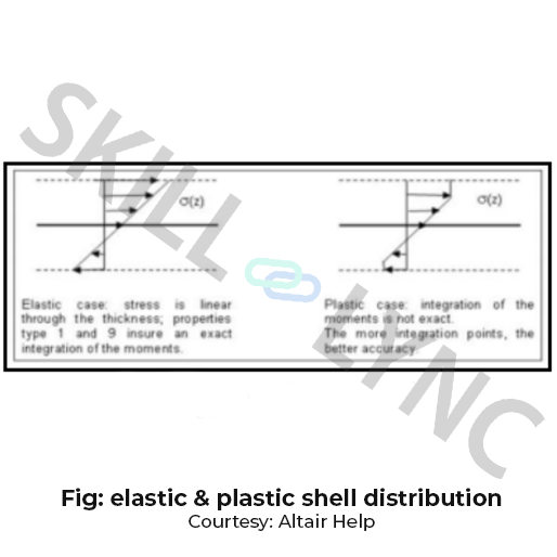
- In the case of elastic behaviour, 3 integration points are enough to obtain the result. The major reason is that stress is linear.
- In the case of plastic behaviour, the stress is not linear, the same bending is not properly integrated throughout the thickness if the element has 3 integration points, to avoid this we go for 5 integration points in the shell elements.
3. Engine stops with the Message:
**ERROR IN OPENING INPUT FILE
- This error occurs if the _0000.rad file contains an improper solver version in it
- Even if the engine file and starter file are in different version formats.
Remedy:
- Based on the radioss solver version used one can change the keyword /VERS/14 to the version being used.
- Make sure the same is followed in the starter file as well. This will eradicate the opening of the input file error.
4. How to get material data from real physical tests like Law24 concrete?
- Get density by weighing the specimen, young’s modulus with a compression test, Poisson coefficient is assumed to be 0.2 approx
- Get ‘fc’ from the compression strength using a cube compression test.
- Inputting the following data will ensure the accuracy of results,
- Get ‘ft’ from the tensile test, it is the direct tensile strength
- Get ft, Ht from the splitting tensile test also called as Brazilian test.
- Get ‘fb’ using biaxial test
- Get f2, s0 from the confined test.
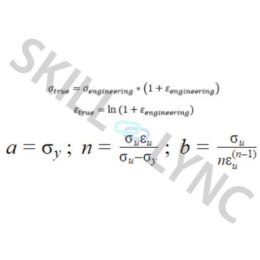
5. What type of curve is to be inputted for Law36?
- The curve is basically a plastic portion of the stress vs strain rates curve. True stress vs strain curve is inputted rather than the experimental ones (engineering curve).
- One can convert the engineering curve to a true stress-strain curve by using the below-mentioned formulas
6. EPSmax in a Solid element does not get deleted when the criteria epsmax is reached. Explain Why.
- Depending on the material law, the solid elements are not deleted after the criteria EPSmax is reached.
- For material Law 2, Law 4 and Law 22, only the deviatoric part of the stress tensor is set to zero, the internal pressure of the solid is still computed.
- On the other hand, for material law 3, Law 23, Law 28 and Law 36, the solid elements are deleted when EPSmax is reached.
7. Does the presence of shell elements mandatory on the surface of the solid elements on the master side while selecting type7?
- Actually, it is not mandatory. Only the external surface of the solid should be defined. It is possible to define the surface of an external skin of a solid part.
- This can be clearly seen when creating a type7 of the interface in frontal crash projects where there is a solid crushable component present in the front of the car being selected for self-impact contact.
8. How are the master side and slave side chosen in type7 contact which is neither self-impacting nor symmetric?
- It is always recommended to choose the coarse mesh on the master side for better contact detection.
- If the mesh of fine size is chosen on the master side, the contact is not detected at all.
9. Error in self-impacting interface type7
WARNING ID: 94
** WARNING IN INTERFACE GAP
INPUT GAP xxx
HOWEVER, GAP IS RECOMMENDED TO BE LESS THAN xxx
- The recommended value corresponds to the smallest side length of shell elements on the master side, divided by 2.
- A self-impacting interface for which the GAP equals half the side length of an element is shown below,
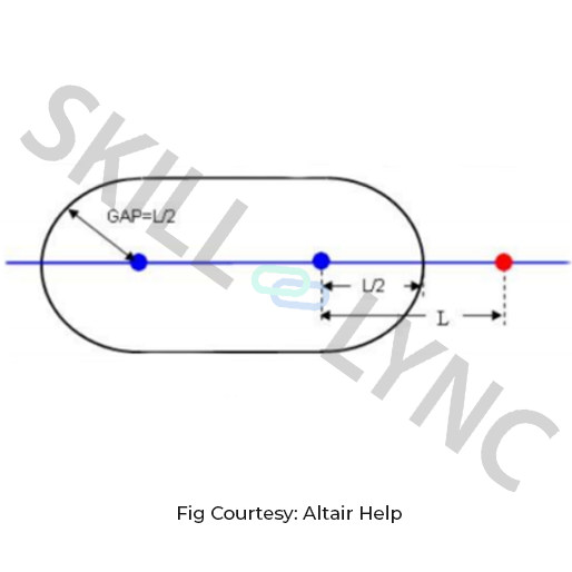
- If this element is compressed more than 50%, the red node enters into the gap of the neighboring element. A self-contact is then detected which leads to over-stiffening of the structure. So the warning message means that at least one element on the master side has a side length less than twice the GAP and there is a risk of over-stiffening.
- If the side length L of an element is lower than the GAP, a self-contact will be computed from the beginning of the computation.
- Such a situation can be accepted if it is local enough, but not if it is a frequent situation over the self-impacting interface. It is possible to find the source of this message by using a preprocessor and selecting the elements through size criteria.
- In case the interface is not self-impacting, possible consequences of this message will be low performance, but the model behaviour will be correct.
10. Errors in Kinematic conditions
WARNING ID: 147
*** WARNING: INCOMPATIBLE KINEMATIC CONDITIONS
- Two kinematic conditions which apply at the same time along non-orthogonal directions are considered incompatible.
- For instance, a boundary constraint on a node in the X direction of the global system and an imposed velocity in the same direction are not compatible. On the other hand, a boundary constraint on a node in the X direction of the global system and an imposed velocity in the Y or Z direction of the global system are compatible. Since a rigid body controls the movement of its slave nodes, a rigid body slave node cannot use another condition.
- Moreover, no error is written by RADIOSS starter better than these warnings, which would prevent running the computation, since the analysis of the compatibility of the kinematic conditions is sometimes more complex than RADIOSS starter can manage. In such cases, the WARNINGS provided the only clue to error termination of the run and it is the user’s responsibility to check the model.
11. Why is it not recommended to set a node of the mesh as the master node of a rigid body?
- It is not recommended because the local system of the master node is not compatible with options imposing rotations. If some elements having rotational stiffness are connected, an incompatibility occurs.
- Depending on the flag ICoG, which is used in the rigid body definition, a lot of mass and inertia can be added locally onto the node; as well as the node can be moved to the centre of mass of the rigid body.
12. What is the ERROR ID: 52 /ALTDACT?
- This is the error which keeps on printing continuously until the solver stops.
- This happens when exporting and importing between hypermesh and hypercrash.
Remedy:
- The remedy is to check for any undefined cards, undefined component collectors, undefined material collectors etc and delete them if there are any.
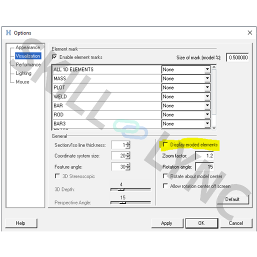
13. How to plot deleted elements to understand the propagation of a fracture?
- In Hyperview, select preferences → Option → Visualization menu in hyper view to display eroded elements as shown below. This will help you to understand the propagation of a fracture.
14. The hourglass energy in the energy error is zero when the QEPH element is used but it is not equal to zero when plotted in the time history. Explain why.
- This is because energy absorbed due to the numerical damping is output there. This means, in output, the place of hourglass energy has been used to present this viscous energy.
- The energy corresponding to the physical stabilization of the hourglass is counted as internal energy for this formulation
15. What are the stresses SIGX, SIGY and VONM in animation files if the integration points are for the shells?
- The stresses SIGX, SIGY in animation files represent the mean stresses through the thickness of the shell element.
- The VONM stress represents the mises criteria applied to these mean stresses SIGX, SIGY. These mean stresses are computed by summation of the stresses at each integration point, averaged by the integration weights. They are used for the calculation of internal forces.
Author

Navin Baskar
Author
Skill-Lync
Subscribe to Our Free Newsletter

Continue Reading
Related Blogs
Learn how to render a shock-tube-simulation and how to work on similar projects after enrolling into anyone of Skill-Lync's CAE courses.
09 May 2020
In this blog, read how to design the frontal BIW enclosure of a car (Bonnet) and learn how Skill-Lync Master's Program in Automotive Design using CATIA V5 will help you get employed as a design engineer.
09 May 2020
Tetrahedral is a four- nodded solid element that can be generated through the tria element by creating a volume and also through the existing volume of the geometry. These elements are used where the geometry has high thickness and complexity. The image attached below is a representation of a Tetra element. The Tetra element will have 4 triangular faces with four nodes joining them together
01 Aug 2022
A connector is a mechanism that specifies how an object (vertex, edge, or face) is connected to another object or the ground. By often simulating the desired behaviour without having to build the precise shape or specify contact circumstances, connectors make modeling simpler.
02 Aug 2022
One of the most crucial processes in carrying out an accurate simulation using FEA is meshing. A mesh is composed of elements that have nodes—coordinate positions in space that might change depending on the element type—that symbolise the geometry's shape.
03 Aug 2022
Author
Skill-Lync
Subscribe to Our Free Newsletter
Continue Reading
Related Blogs
Learn how to render a shock-tube-simulation and how to work on similar projects after enrolling into anyone of Skill-Lync's CAE courses.
09 May 2020
In this blog, read how to design the frontal BIW enclosure of a car (Bonnet) and learn how Skill-Lync Master's Program in Automotive Design using CATIA V5 will help you get employed as a design engineer.
09 May 2020
Tetrahedral is a four- nodded solid element that can be generated through the tria element by creating a volume and also through the existing volume of the geometry. These elements are used where the geometry has high thickness and complexity. The image attached below is a representation of a Tetra element. The Tetra element will have 4 triangular faces with four nodes joining them together
01 Aug 2022
A connector is a mechanism that specifies how an object (vertex, edge, or face) is connected to another object or the ground. By often simulating the desired behaviour without having to build the precise shape or specify contact circumstances, connectors make modeling simpler.
02 Aug 2022
One of the most crucial processes in carrying out an accurate simulation using FEA is meshing. A mesh is composed of elements that have nodes—coordinate positions in space that might change depending on the element type—that symbolise the geometry's shape.
03 Aug 2022
Related Courses


