Project - Speed Control of a Direct Current (DC) motor
In this project, a Simulink model for the DC motor will be first developed per the schematic shown in Figure 1.
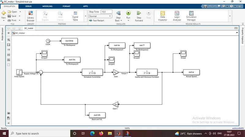
The model is prepared as the DC_motor equations.
The blocks used are clock, workspace,step block, integrator,laplace tranfer,gain and scope block .
Initial values without PID control
J = 0.01; % Moment of inertia of the rotor in kg-m^2
B = 0.1; % Motor viscous friction constant in N-m-s
Km = 0.01; % Back EMF constant in V/rad/s
Kt = 0.01; % Motor torque constant in N-m/amp
R = 1; % resistance of the armature circuit in ohms
L = 0.5; % Inductuce of the armature circuit in henries
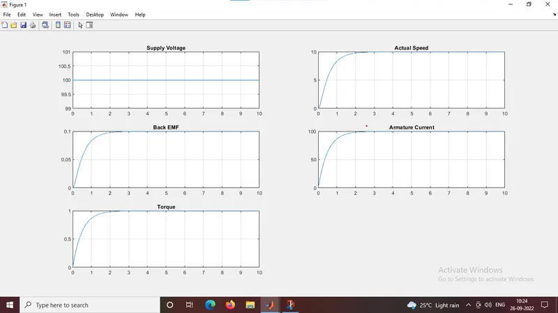
Results:
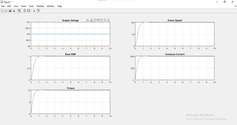
The graph shows 100V values
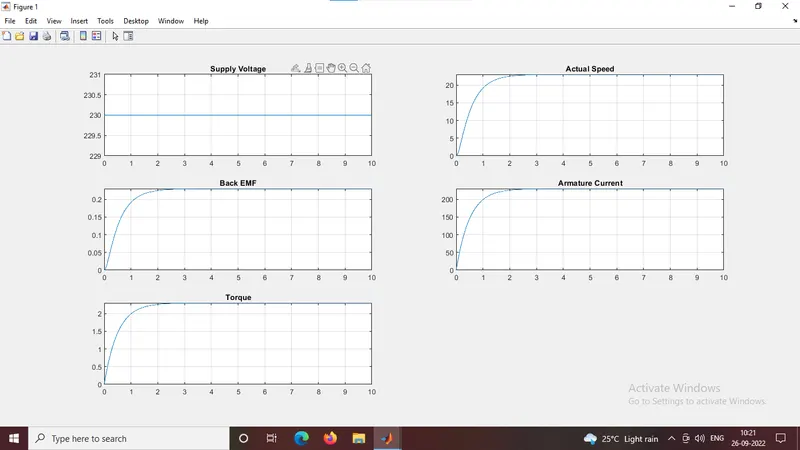
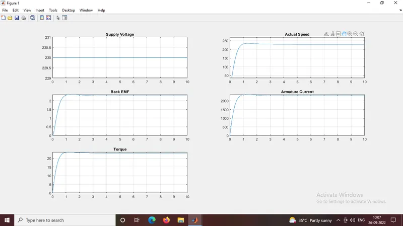
The below graph shows the results for 230V
b)The Proportional, Integral, and Derivative (PID) control design knowledge gained in the training to design, develop and test a controller to maintain a desired speed for the motor.
The inital values were taken using the pole and place command to find the values of the Kp,Kd and later manually selected the Ki values
>> K_motor
K_motor =
13.1892 -0.3480
>> P
P =
-5.6520 + 2.7374i -5.6520 - 2.7374i
>> p1
p1 =
-5.6520 + 2.7374i
>> p2
p2 =
-5.6520 - 2.7374i
Ki=20
Kp=13.189
Kd=-0.348
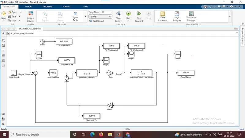
The simulink model shows the PID design of the motor
s = tf('s');
P = Km/((J*s+B)*(L*s + R)+(Kt^2));
zeta = 0.9;
fn=1.0; % Frequency of the motor in Hz
wn= 6.28;
% Vector of the motor
A_motor = [-B/J Km/J ; -Km/L -R/L];
B_motor = [0 ; 1/L];
c = [1 0];
d = 0;
% Poles and K values for the system
p1 = -zeta*wn+wn*sqrt(zeta^2-1);
p2 = -zeta*wn-wn*sqrt(zeta^2-1);
P = [p1 p2];
K_motor= place(A_motor,B_motor,P);
>> K_motor
K_motor =
13.1892 -0.3480
>> P
P =
-5.6520 + 2.7374i -5.6520 - 2.7374i
>> p1
p1 =
-5.6520 + 2.7374i
>> p2
p2 =
-5.6520 - 2.7374i
Results:
The following results shows for 100V using PID controller
The results shows for 230V
The Kp=13.189, Kd=-0.348, and Ki=20