Project 1 - Controlling a DC motor using PWM and monitoring its Running status
Project 1 - Controlling a DC motor using PWM and monitoring its Running status
Overview of the Project:
Implement a system on the simulator for controlling a DC motor using L293 motor driver, monitor its status and print the running status of motor on the LCD Display.
Goals:
- Implement a system on simulator for Controlling the DC motor using L293 motor driver.
- Displaying the running status of DC motor on the LCD display.
Key Highlights of the Project:
- The DC motor can be controlled by using L293 motor driver.
- The speed of a DC motor can be controlled by varying its input voltage, for doing this is to use PWM (Pulse Width Modulation).
- L293D IC is a typical Motor Driver IC which allows the DC motor to drive on any direction.
Deliverables of this project:
- Implement the system for controlling DC motor.
- Controlling the speed of the DC motor using PMW.
- Displaying the present running status of DC machine on LCD display.
Expected Outcomes:
- Implement a system on simulator to control a DC motor using PMW
- Monitoring the running status of the DC motor using L293 motor driver which allows the DC motor to drive on any direction.
- Running status i.e. on which direction the DC motor is running is to be displayed on the LCD screen.
MOTOR DC
A DC motor is any of a class of rotary electrical motor hat converts direct current (DC) electrical energy into mechanical energy. The most common types rely on the forces produced by magnetic fields. Nearly all types of DC motors have some internal mechanism, either electromechanical or electronic, to periodically change the direction of current in part of the motor.
L293 Motor driver
he L293D is a 16-pin Motor Driver IC which can control a set of two DC motors simultaneously in any direction. The L293D is designed to provide bidirectional drive currents of up to 600 mA (per channel) at voltages from 4.5 V to 36 V (at pin 8!). You can use it to control small dc motors - toy motors.
CODE
/*
* Project1_.c
*
* Created: 03-11-2022 16:20:20
* Author : Vedang More
*/
#include <avr/io.h> //AVR Preprocessor I/o library
#define F_CPU 16000000ul //CPU Frequency
#include "avr/interrupt.h" //Interrupt library Function
#include <util/delay.h> //Delay Function
#define sw_dir (PIND&(1<<1)) //D1 pin enabled as switch button for motor direction control.
#define sw_spd (PIND&(1<<2)) //D2 pin enabled as switch button for motor speed control.
#define pw (PINC&(1<<3)) //C3 pin enabled as switch button for motor On/Off control.
#define lcd_port PORTB //PORTB set for LCD o/p
unsigned char i; //Variable declaration to increase duty cycle
#define RS_high PORTD|=(1<<5); //Pin5 used as RS High
#define RS_low PORTD&=~(1<<5);//Pin5 used as RS Low
#define EN_high PORTD|=(1<<6); //Pin6 enabled as High
#define EN_low PORTD&=~(1<<6);//Pin6 enabled as Low
void lcd_cmd(char cmd) //LCD command function
{
lcd_port=(cmd&0xf0); // Masking 4 bits for 4 bit LCD mode
RS_low;
EN_low;
_delay_ms(1);
EN_high;
lcd_port=((cmd<<4)&(0xf0));
RS_low;
EN_low;
_delay_ms(1);
EN_high;
}
void lcd_data(char data) //LCD function to send data
{
lcd_port=(data &0xf0);
RS_high;
EN_low;
_delay_ms(1);
EN_high;
lcd_port=((data<<4)&(0xf0));
RS_high;
EN_low;
_delay_ms(1);
EN_high;
}
void lcd_init()
{
lcd_cmd(0x02);_delay_ms(5);//Return the cursor to home
lcd_cmd(0x01);_delay_ms(5); //Clear screen
lcd_cmd(0x0C);_delay_ms(5);//Display ON cursor OFF
lcd_cmd(0x06);_delay_ms(5);//Increment cursor
lcd_cmd(0x80);_delay_ms(5);//Force cursor to begin 1st line
lcd_cmd(0x28);_delay_ms(5);//Used for 4 bits lcd mode
}
void cursorpos(char x, char y) //LCD cirsor positin fubction
{
if ((x<1||x>2)||(y>16||y<1)) // Execution if loop
{
x=1;
y=1;
}
if (x==1)
{
lcd_cmd(0x7f+y);
}
else
{
lcd_cmd(0xBF+y);
} }
void lcd_out(char x, char y, char *str) //LCD function to passing string
{
cursorpos(x,y);
while (*str)
{
lcd_data(*str);
str++;
} }
int main() //Main function
{
DDRB=0xFF; //Data directive register is enabled
DDRA|=((1<<0)|(1<<1)); //PORT 0 and 1 is enabled
DDRD&=~(1<<1); //PORT D1 is reset
DDRD&=~(1<<2);
DDRD|=(1<<5);
DDRD|=(1<<6);
DDRC&=~(1<<3);
PORTD|=(1<<2);
PORTC|=(1<<3);
i=64;
TCCR0=0X61;
GICR=(1<<INT0);
MCUCR=0X02;
sei();
lcd_init();
while (1)
{
while(pw==0)
{
if (sw_dir==0)
{
PORTA=0b00000001;
lcd_out(1,1,"Motor is Running");
lcd_out(2,3,"Clockwise");
}
else
{
PORTA=0b00000010;
lcd_out(1,1,"Motor is Running");
lcd_out(2,3,"Anticlockwise");
}
OCR0=i;
}
PORTA=0x00;
lcd_out(1,1,"Motor is Off");
lcd_out(2,3,"Caution !!!!!");
}
}
ISR(INT0_vect) //Interrupt service routine 0
{
i=i+20;
}
output
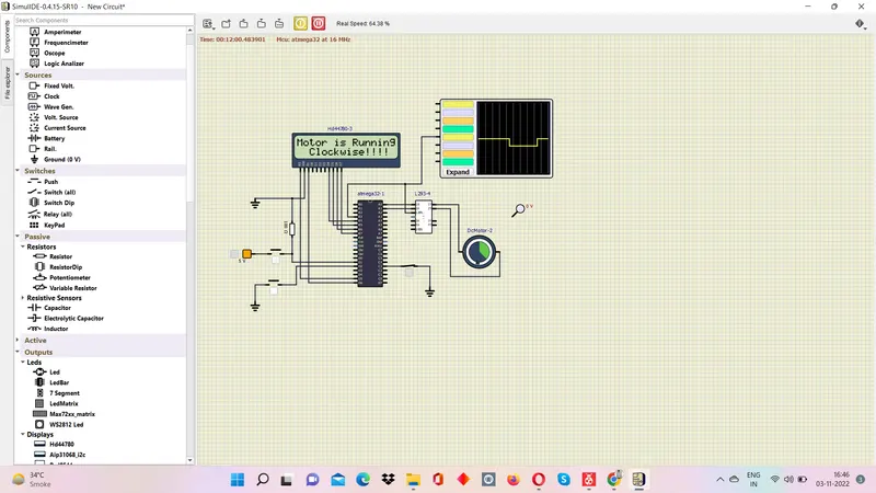
Motor is running clock wise
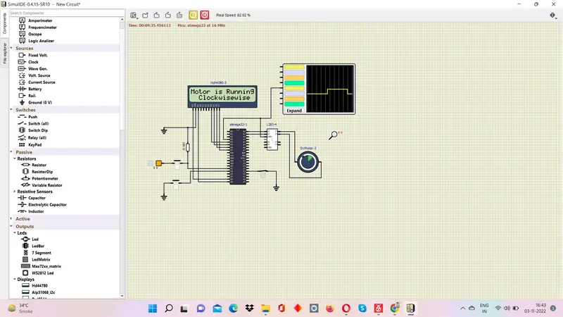
Motor running anticlock wise
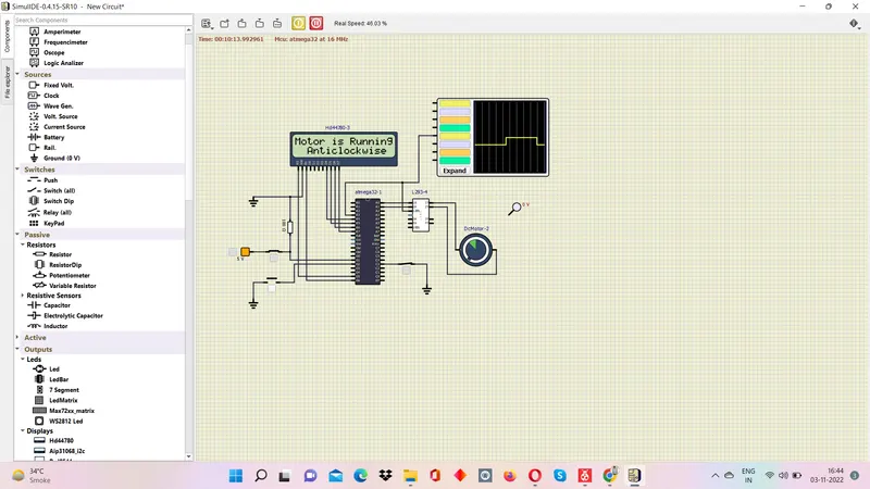
Motor turned Off
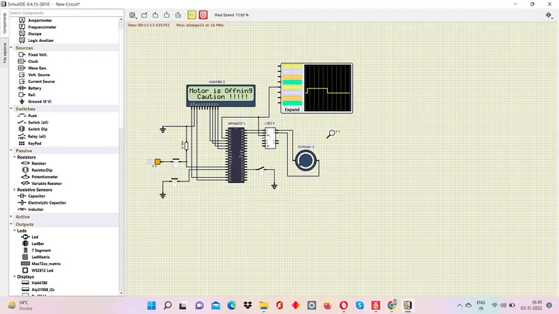
Motor turned ON Running in Clockwise direction and Speed is high