Frequency Analysis of a rotating shaft
Frequency Analysis of a rotating shaft (SOLIDWORKS)
1. OBJECTIVES
Find out the critical frequencies of a rotating shaft in Solidworks by creating the Shaft model in Solidworks.
Conduct a frequency analysis and apply a bearing fixture on the stepped face of the rod at the two ends and perform the analysis.
Find out 5 mode shapes and list the resonant frequencies
2. THEORY
Natural frequency - The frequency at which a system oscillates when not subjected to a continuous or repeated external force.
Resonant frequency - Resonant frequency is the oscillation of a system at its natural or unforced resonance. Resonance occurs when a system is able to store and easily transfer energy between different storage modes, such as kinetic energy or potential energy as you would find with a simple pendulum.
Resonance – The increase in amplitude of oscillation of an electric or mechanical system exposed to a periodic force whose frequency is equal or very close to the natural undamped frequency of the system.
Mode – The mode is a statistical term that refers to the most frequently occurring number found in a set of numbers. The mode is found by collecting and organizing data in order to count the frequency of each result. The result with the highest count of occurrences is the mode of the set, also referred to as the modal value.
A mode shape is a specific pattern of vibration executed by a mechanical system at a specific frequency. Different mode shapes will be associated with different frequencies. The experimental technique of modal analysis discovers these mode shapes and the frequencies.
Modes are inherent properties of a structure and are determined by the material properties (mass, damping and stiffness) and boundary conditions of the structure. Each mode is defined by a natural (modal or resonant) frequency, modal damping and a mode shape (i.e. the so called Modal parameters).
Critical Speed of Shafts
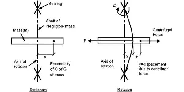
The critical speed is the theoretical angular velocity which excites the natural frequency of a rotating object, such as a shaft. As the speed of rotation approaches the objects natural frequency, the object begins to resonate which dramatically increases systemic vibration. The resulting resonance occurs regardless of orientation.
When the rotational speed is equal to the numerical value of the natural vibration then that speed is called critical speed.
For a rotating shaft there is a speed at which, for any small initial deflection, the centrifugal force is equal to the elastic restoring force. At this point the deflection increases greatly and the shaft is said to "whirl". Below and above this speed this effect is very much reduced. This critical (whirling speed) is dependent on the shaft dimensions, the shaft material and the shaft loads.
All rotating shafts, even in the absence of external load, deflect during rotation. No shaft is perfectly straight and no shaft with attached masses is perfectly statically balanced such that the centre of gravity coincides with the axis of rotation.
At Morse Air Systems, we calculate the critical speed of our fan designs. We ensure the operation speed is at least 20 % either side of the calculated critical speed. This will result in the fan running well outside the "danger zone".
3. PROCEDURE
1. Create the shaft model in SolidWorks.
- 2D sketch
- 3D model
- Volumetric properties of the shaft
2. Create a new simulation and select frequency simulation option.
3. Select Alloy steel as an material.
4. Set the fixtures at the stepped face of the rod at the two ends.
5. Create mesh of size 5 mm.
6. Run the simulation by setting the no of frequency as 5 in frequency property (which is default value).
4. RESULTS
MODE -1
In this mode shaft vibrates along Y axis.
MODE -2
In this mode shaft vibrates along X axis.
MODE - 3
In this mode shaft vibrates on XY plane.
MODE - 4
In this mode shaft vibrates about Y axis.
MODE - 5
In this mode shaft vibrates about X axis.
RESONANT / CRITICAL FREQUENCY LIST
5. CONCLUSION
- 1st and 2nd mode has same critcal frequecy.
- 3rd and 4th mode has same critcal frequecy.
- If the shaft riches to the frequency of one of the above critical frequecy it will fail.
-
The mode shape and natural frequency values give the direction in which external frequency should be applied and the allowable excitation frequency can be applied.But generally external frequency cannot be controlled, so we need to alter the natural frequency of the component itself by varying its mass and stiffness.
Google Drive Link - https://drive.google.com/drive/folders/1I1AGPXkLMLrAj2kPdGCfYBak9YFuyJQw?usp=sharing